ARI Armaturen DP34 EN User Manual
Page 14
Page 14
0040504000 1210
Operating and installation instructions
Pneumatic actuators - DP32 / DP33 / DP34
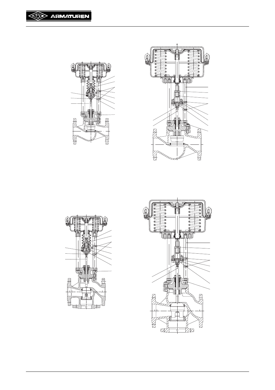
Fig. 18: Pneumatic straight through control valve
Operating mode of the actuator: „actuator stem retracts by spring force“
Spring opens on air failure.
Fig. 19: Pneumatic three-way control valve as a mixing valve (path AB-B)
Operating mode of the actuator: „actuator stem retracts by spring force“
Spring opens on air failure.
Valve stem
Locking nut
Hexagon nut
Securing flange
Coupling flange
Locking nut
Distance column
Valve stem
Locking nut
Hexagon nut
Thread bush
Travel indicator
Securing flange
Coupling flange
Locking nut
Distance column
Coupling
Set screw
(90°rotated view)
Travel indicator
Thread bush
Cylinder screw
DP 32 - 33
DP 34
Valve stem
Locking nut
Hexagon nut
Cylinder screw
Coupling flange
Locking nut
Distance column
Valve stem
Locking nut
Hexagon nut
Thread bush
Travel indicator
Securing flange
Coupling flange
Locking nut
Distance column
Coupling
Set screw
(90°rotated view)
Travel indicator
Thread bush
Securing flange
DP 32 - 33
DP 34