2 terminal assignments, 3 connection conditions – ARI Armaturen ES11 EN User Manual
Page 9
Rev. 0040601000 1014
Page 2-9
Operating and installation instructions
Electronic positioner ES11
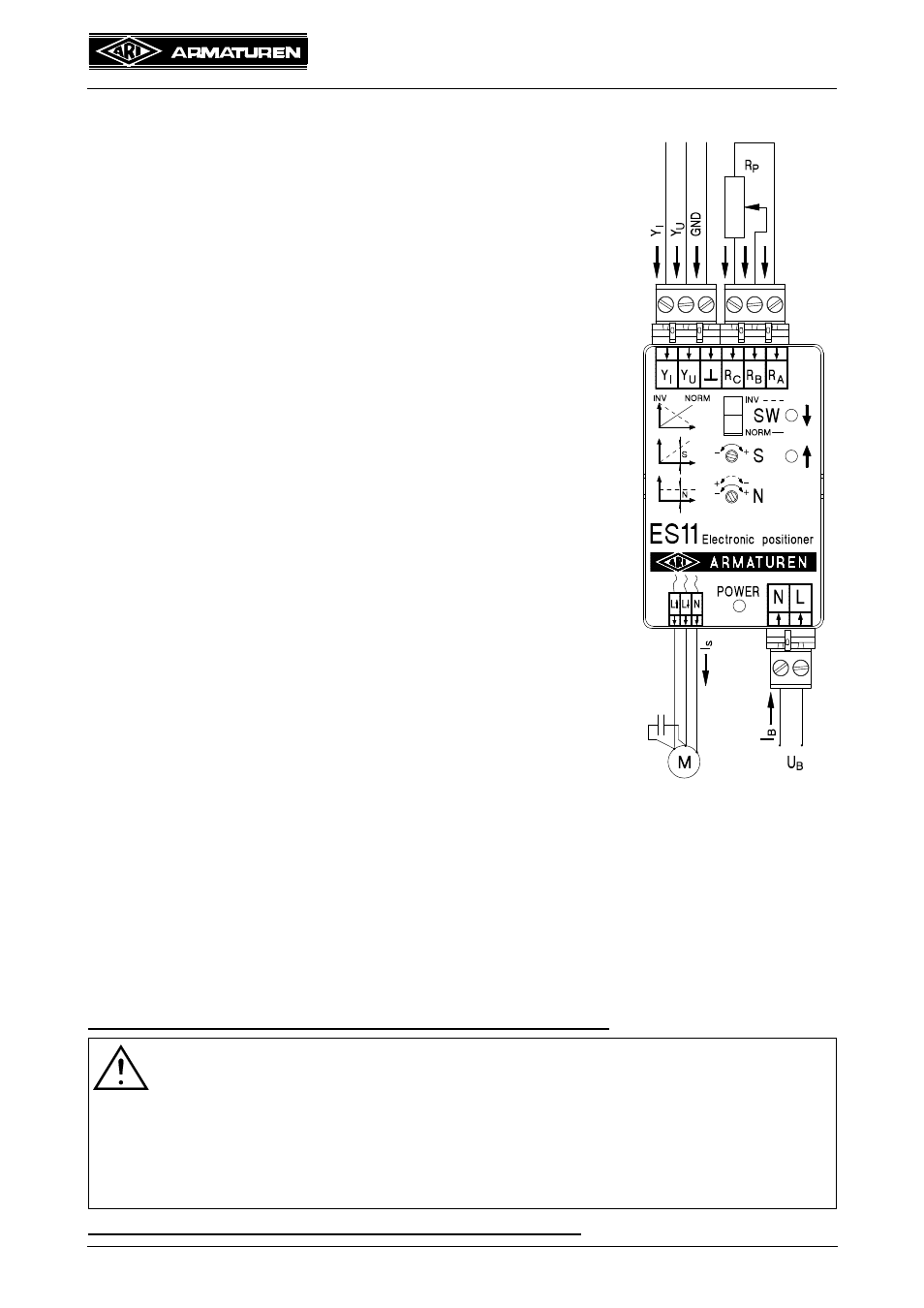
5.5.2 Terminal assignments
Power input
N ............Terminal - power input ....................... Neutral
conductor
L ............Terminal - power input ....................... Phase
Actuating signal input
Y
I
Terminal - input signal........................ +...20 mA DC
Y
U
Terminal - input signal........................ +...10 V DC
............Terminal - ground, GND..................... 0 V
Potentiometer input
R
P
Potentiometer ................................... 0...1000
R
A
Terminal - potentiometer input .......... (yellow wire)
R
B
Terminal - potentiometer input .......... (grey wire)
R
C
Terminal - potentiometer input ........... (red wire)
Three-step actuating signal output
(via cable with isolating terminal to actuator)
L
.......... black (violet), phase switched in open direction
L
..........brown, phase switched in close direction
N ............blue, neutral conductor
AC motor
M............AC motor with start-up capacitor
Fig. 5
5.5.3 Connection conditions
All electrical terminals are connected to the ES11 by means of series isolating terminals.
The suitable conductor cross-sections for connecting the terminals are 0.2 to 2.5 mm
2
. To
achieve optimal electromagnetic compatibility it is recommended to use shielded cables for
connecting potentiometers or standardized active current or voltage signals.
Electromagnetic interference (EMI) on the actuating signal Y
I
or Y
U
can be
suppressed to a great extent by subsequently installing a filter to the actuating
signal input.
Please contact the manufacturer direct for technical information.
ATTENTION !
To facilitate use in 3-conductor technology, the ground input
may be connected
to the N contact of the power input only in the 24 V AC version.
The new contact is then referred to as zero potential (0V).
If installed in a 3-conductor technology with strong electromagnetic influence this
can lead to disturbances. In this case don‘t join the ground input
with the
mainfuse N.
Fuse protection of mains power supply on system side: 6 A max.
............
..........
..........
..........
..........
..........