1 factory setting, 2 setting of potentiometer, 3 type of control signal – ARI Armaturen ES11 EN User Manual
Page 18: 4 setting of effective direction sw
Page 2-18
Rev. 0040601000 1014
Operating and installation instructions
Electronic positioner ES11
6.1 Factory setting
Upon delivery of the ES11 with a cpl. control device (valve and actuator), the potentiometer
and the ES11 are adjusted by factory to it’s valve travel. The factory setting is indicated with
a waterproof marker or a sticker on the nameplate.
If the order was given without indication of a special control signal, the default is 4-20mA.
4mA for a closed valve.
6.2 Setting of potentiometer
a) To adjust the potentiometer in the actuator, the operating instructions of the
corresponding actuator have to be observed.
b) Switch-off mains voltage and secure against unintentional reconnection.
c) Turn the potentiometer to 0 Ohm position.
- At PREMIO-actuator turn the potentiometer spindle counter-clockwise until it stops
(0 Ohm position).
- For inspection, the resistance of the potentiometer must be measured with an
ohmmeter.
For resistance measurement disconnect the potentiometer from the ES11 positioner.
First measurement contact ................R
B
- grey cable...... - PREMIO terminal 26 (29)
Second measurement contact ...........R
C
- red cable........ - PREMIO terminal 25 (28)
With completely extended actuator spindle, it must be approx. 0 Ohm between the first
and second measuring contact.
d) Turn thrust actuator with manual handwheel into cpl. retracted position and read the
corresponding resistance value at the Ohmmeter.
- With cpl. retracted actuator stem, 750th...1100 Ohm must lie between the first and
second measuring contact.
e) Connect the potentiometer with the ES11 positioner again.
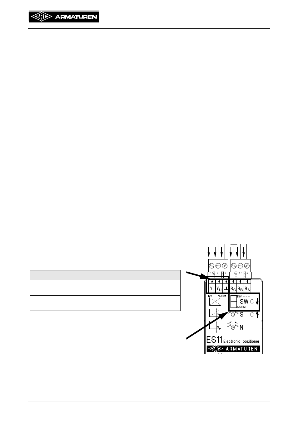
6.3 Type of control signal
The selection of the required control signal, is done by
corresponding clamp connection.
Type of control signal
clamp connection at:
Voltage signal
max. 10 V DC for e.g. 0-10V
YU and GND
Current signal
max. 20mA DC for e.g. 4-20mA
YI and GND
It may be only one control signal connected.
6.4 Setting of effective direction SW
At the switch SW, the effective direction of the control
signal is adjusted to the thrust direction.
Take the switch to the desired position.
Fig. 10