5 zero point setting, 5 zero point setting -19, Efer to 6.5 – ARI Armaturen ES11 EN User Manual
Page 19
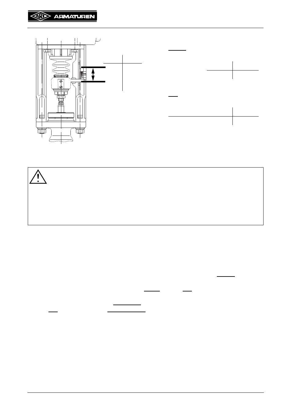
Fig. 11: Effective direction
NORM:
INV:
Example:
Control signal
max.
10V
20mA
min.
0V
4mA
Example:
Control signal
min.
0V
4mA
max.
10V
20mA
Control signal
NORM
INV
max.
min.
min.
max.
Rev. 0040601000 1014
Page 2-19
Operating and installation instructions
Electronic positioner ES11
6.5 Zero point setting
ATTENTION !
- Observe the order of the settings:
1. Potentiometer (refer to 6.2)
2. Effective direction (refer to 6.4)
3. Zero point (refer to 6.5)
4. Slope span (refer to 6.6)
- In case of subsequent changes to a setting, the following settings must be
readjusted!
a) The voltage supply must be disconnected before carrying out any setting work.
b) Turn the valve stem with the handwheel for the min. control signal in the desired position,
e.g. 4mA or 0V, (according to the switch position SW and as shown in Fig. 11 : Effective
direction). Typically this will be the closed valve.
c) Set the input signal to the minimum required value, e.g. 4 mA or 0 V.
d) Disconnect the line separating terminal X25 or X28 to the motor and let it be separated.
e) Connect voltage at L and N from the 2-pin series isolating terminal, the yellow LED must
be lit.
f) Turn zero point adjusting screw N until the green and the red LEDs are no longer lit (the
slip clutch cuts in after 25 turns).
If the green LED lights, turn in clockwise direction.
If the red LED lights, turn in anticlockwise direction.
g) If the actuator is at an end position and should it be switched-off by actuating force at this
position, turn the zero point adjusting screw N, so that the green LED lights up just before
it’s release operating point.