Installation and connection, Pax manual mode registers – Red Lion PAXCDC5 (PROFIBUS) User Manual
Page 4
CSR - Control Status Register (PAX Analog Only)
The Control Status Register is used to directly control the meter’s outputs
(setpoints and analog output), or view the state of the setpoint outputs and the
status of the temperature sensor (PAXT only). The CSR register is bit mapped,
with the bit positions of the least-significant byte assigned to specific control
functions. The control functions are invoked by writing to the appropriate bit
position. The bit position definitions are:
Setting bit 4 of the CSR selects Manual Mode. In this mode, the setpoint
outputs are defined by the values written to bits b0, b1, b2, b3; and the analog
output is defined by the value written to the Analog Output Register (AOR).
Internal control of these outputs is then overridden.
In Automatic Mode, the setpoint outputs can only be Reset off. The contents
of the CSR may be read to interrogate the state of the setpoint outputs and to
check the status of the temperature sensor (PAXT only).
MMR - Auto/Manual Mode Register
(PAXDP/PAX2A/PAXI/PAXDR/PAXCK)
This register sets the controlling mode for each output in the PAX meters.
Each output may be independently changed to Auto or Manual mode. The MMR
register is bit mapped, with the bit positions of the least-significant byte
assigned to specific outputs. Auto or Manual mode is selected by writing to the
appropriate bit position. The bit position definitions are:
0 = Auto Mode, 1 = Manual Mode
In Auto Mode (0) the meter controls the setpoint output state and the Analog
Output (PAXDP/PAX2A/PAXI/PAXDR only). In Manual Mode (1) the setpoint
outputs are defined by the value in the Setpoint Output Register (SOR); and the
Analog Output is defined by the value written to the Analog Output Register
(AOR). When transferring from Auto Mode to Manual Mode, the meter holds
the last output value (until the register is changed by a write).
SOR - Setpoint Output Register
(PAXDP/PAX2A/PAXI/PAXDR/PAXCK)
The Setpoint Output Register is used to view or change the states of the
setpoint outputs in the PAX meters. Reading this register will show the present
state of all the setpoint outputs. A “0” means the output is inactive and a “1”
means the output is active.
In Auto Mode (see MMR description), the meter controls the setpoint output
state. In Manual Mode, the four least-significant bits of the SOR are assigned to
specific outputs. Writing to the appropriate bit position defines the state of the
setpoint output. The bit position definitions are:
(AOR) Analog Output Register (Not applicable to PAXCK)
The Analog Output Register value defines the signal level of the meter’s
analog output. The range of values for this register is 0 to 4095 (0FFFh), which
corresponds to the analog output signal ranges shown in Table 4.
*Due to the absolute accuracy
rating and resolution of the
output card, the actual output
signal may differ 0.15% FS from
the table values. The output
signal corresponds to the range
selected (0-20 mA or 0-10 V).
In Automatic mode, the meter controls the analog output signal level.
Reading the AOR will show the present value of the analog output signal. While
in Automatic mode, this register may be written to, but it has no effect until the
analog output is placed in the Manual mode.
In Manual mode, writing to the AOR causes the analog output signal level to
update per the value written. Manual mode is engaged by setting bit 4 of the
CSR (PAX Analog meter) or bit 0 of the MMR (PAXDP/PAX2A/PAXI/
PAXDR). If a value larger than 4095 is written to the AOR, 4095 will be loaded.
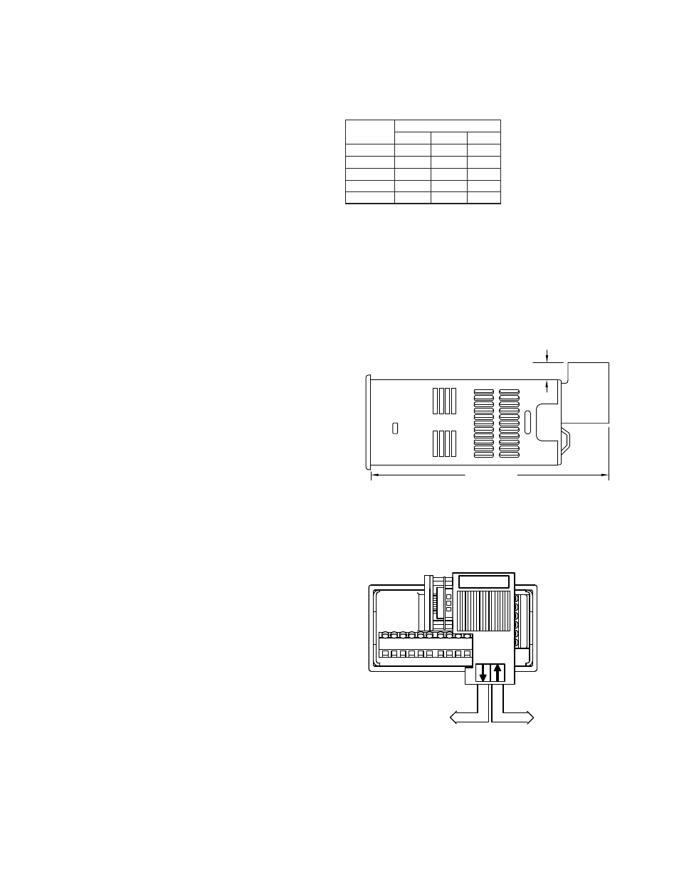
INSTALLATION AND CONNECTION
Installation Clearance Required - In Inches (mm)
PROFIBUS-DP Network Connection
PROFIBUS plug connectors such as Siemens 6ES7 972-0BA10-0XA0 are
recommended. When wiring the connector, be sure to observe the proper
direction for data flows, indicated by the arrows on the connector. When the
PAX meter is the last device on the network, set the terminating resistor switch
on the connector to the “ON” position.
PAX MANUAL MODE REGISTERS
bit 0: Analog Output
bit 0: Setpoint 4 Output
bit 1: Setpoint 4 Output
bit 1: Setpoint 3 Output
bit 2: Setpoint 3 Output
bit 2: Setpoint 2 Output
bit 3: Setpoint 2 Output
bit 3: Setpoint 1 Output
bit 4: Setpoint 1 Output
bit 0: Setpoint 4 Output Status
bit 1: Setpoint 3 Output Status
0 = Output Off
bit 2: Setpoint 2 Output Status
1 = Output On
bit 3: Setpoint 1 Output Status
Table 4 - Analog Output Signal Ranges
.35 (9)
4.88 (124)
1
2
4
3
6
5
7
9
8
10
to upstream
PROFIBUS Network
to downstream
PROFIBUS Network
1 = manual mode
0 = automatic mode
bit 4: Auto/Manual Mode
bit 3: Setpoint 4 Output
bit 2: Setpoint 3 Output
bit 1: Setpoint 2 Output
bit 7: Unused (always stays 0)
1 = sensor fail
0 = sensor normal
bit 6: Sensor Status (PAXT only)
bit 5: Unused (always stays 0)
bit 0: Setpoint 1 Output
0 = output off
1 = output on
PAXDP/PAX2A/PAXI/PAXDR
PAXCK
4-20 mA
0-20 mA
20.000
20.000
10.000
19.996
9.9975
19.995
12.000
5.000
10.000
0.005
4.004
0.0025
4.000
0.000
0.000
0-10 V
Output Signal*
4095
4094
2047
0
Register
Value
1
Red Lion Controls
Headquarters
20 Willow Springs Circle
York PA 17406
Tel +1 (717) 767-6511
Fax +1 (717) 764-0839
Red Lion Controls
China
Unit 101, XinAn Plaza
Building 13, No.99 Tianzhou Road
ShangHai, P.R. China 200223
Tel +86 21 6113-3688
Fax +86 21 6113-3683
Red Lion Controls
Europe
Printerweg 10
NL - 3821 AD Amersfoort
Tel +31 (0) 334 723 225
Fax +31 (0) 334 893 793
Red Lion Controls
India
54, Vishvas Tenement
GST Road, New Ranip,
Ahmedabad-382480 Gujarat, India
Tel +91 987 954 0503
Fax +91 79 275 31 350