Parameterization, Configuration, Data exchange – Red Lion PAXCDC5 (PROFIBUS) User Manual
Page 3: Demand write and store request masks, Data block structure
3
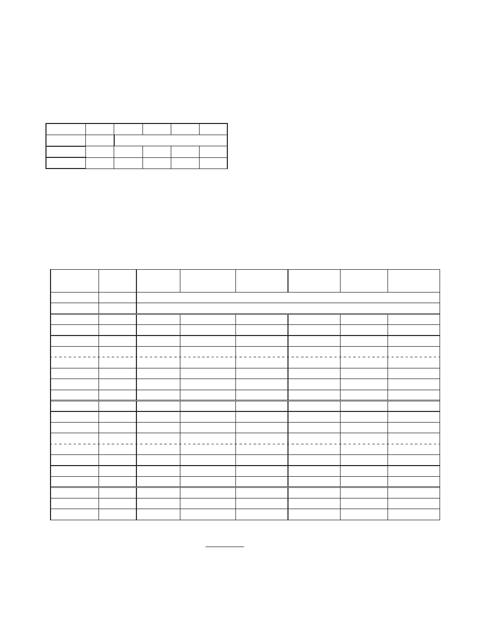
Table 3 - Data Block Structure
REGISTER INDEX
(Mask Bit)
DATA BLOCK
BYTES
PAX ANALOG
INPUT METER
(5-Digit)
PAXDP ANALOG
INPUT METER
(5-Digit) ****
PAX2A ANALOG
INPUT METER
(6-Digit) ****
PAXI DIGITAL
COUNT / RATE
(6-Digit)
PAXDR DIGITAL
DUAL RATE
(6-Digit)
PAXCK DIGITAL
CLOCK / TIMER
(6-Digit)
-
1 - 4
Demand Write Mask (Output) / Service Status (Input)
-
5 - 8
Store Mask (Output) / Unused (Input)
0
9 - 12
Input *
Input A (relative) *
Input (relative) *
Count A
Rate A *
Timer
1
13 - 16
Total *
Input B (relative) *
Total *
Count B
Rate B *
Counter
2
17 - 20
Max. Input *
Calculation *
Max. Input *
Count C
Rate C *
RTC Time
3
21 - 24
Min. Input *
Total *
Min. Input *
Rate
Total A
RTC Date
4
25 - 28
Setpoint 1
Min Input *
Setpoint 1
Min. Rate
Total B
Setpoint 1
5
29 - 32
Setpoint 2
Max Input *
Setpoint 2
Max. Rate
Total C *
Setpoint 2
6
33 - 36
Setpoint 3
Input A (absolute) *
Setpoint 3
Scale Factor A
Scale Factor A
Setpoint 3
7
37 - 40
Setpoint 4
Input B (absolute) *
Setpoint 4
Scale Factor B
Scale Factor B
Setpoint 4
8
41 - 44
AOR **
Input A (offset)
Band/Deviation 1
Scale Factor C
Scale Factor C
Setpoint Off 1
9
45 - 48
CSR **
Input B (offset)
Band/Deviation 2
Count Load A
Count Load A
Setpoint Off 2
10
49 - 52
----
***
Band/Deviation 3
Count Load B
Count Load B
Setpoint Off 3
11
53 - 56
----
***
Band/Deviation 4
Count Load C
***
Setpoint Off 4
12
57 - 60
----
Setpoint 1
Input (absolute) *
Setpoint 1
Setpoint 1
Timer Start
13
61 - 64
----
Setpoint 2
Input Offset
Setpoint 2
Setpoint 2
Counter Start
14
65 - 68
----
Setpoint 3
***
Setpoint 3
Setpoint 3
Timer Stop
15
69 - 72
----
Setpoint 4
***
Setpoint 4
Setpoint 4
Counter Stop
16
73 - 76
----
MMR **
MMR **
MMR **
MMR **
MMR **
17
77 - 80
----
AOR **
AOR **
AOR **
AOR **
RTC Day
18
81 - 84
----
SOR **
SOR **
SOR **
SOR **
SOR **
* Indicates Read-Only parameters. All other parameters are Read/Write.
** Indicates PAX Manual Mode Registers. See next section for description.
*** Indicates bit value must not be set in the Parameterization polled read mask.
**** Select “PAX Digital (6-digit)” module for full mapping of the available registers.
PARAMETERIZATION
The Polled Read Mask defines which PAX registers will be polled by the card
and therefore updated in the Input Data Block. The Polled Read Mask is a 32-bit
integer with each bit mapped to a PAX register index. The Polled Read Mask is
configured in the card by the Master sending a Parameterization telegram with
4 bytes of User Parameter Data representing the Polled Read Mask, in Motorola
byte ordering.
Table 2 shows the User Parameter bytes representing the Polled Read Mask
and gives the default value and a typical example. The default Polled Read
Mask indicates PAX register index 0 will be updated in the Input Block. The
example Polled Read Mask indicates that PAX registers 0 and 8 will be updated
in the Input Block.
Table 2 - User Parameter Data
CONFIGURATION
Configuration of the Data Block is by the selection of pre-configured
modules, identified in the GSD file as “PAX Digital (6-digit)” and “PAX Analog
(5-digit)”. They differ in the number of registers available and therefore the size
of the Data Block required to map all the registers completely. Each PAX
register is represented as a 32-bit Integer requiring 2, 16-bit words or 4 bytes.
DATA EXCHANGE
Demand Write and Store Request Masks
The Demand Write Mask defines how data is written to the PAX. The
Demand Write Mask is a 32-bit integer with each bit mapped to a PAX register
index. Setting a bit in the Demand Write Mask of the Output Data Block will
force the corresponding register to be written “once only” to the PAX. Clearing
and re-setting the bit will cause the value to be written again. The Demand Write
Mask is part of the Data Block structure.
The Write Service Status register in the Input Data Block reports when the
register has been written to the PAX by setting the corresponding bit. By
monitoring this register a PLC program can detect when the Output Data has
been serviced. The bit will be cleared in the Service Status register when the
corresponding bit is cleared in the Demand Write Mask.
The Store Mask defines how the written value is to be stored in the PAX. The
PAX meters have some values stored in EEPROM so they may power up in the
last saved state. For values that change often it is possible to exceed the life of
an EEPROM with repeated writes to the same address location - this method
inhibits writes to EEPROM. The Store Mask is a 32-bit integer with each bit
mapped to a PAX register index. Setting a bit will inhibit the corresponding
register from being saved to EEPROM.
Data Block Structure
Table 3 shows the Data Block Structure, consisting of the Write and Store
Masks and the individual PAX Data Registers. Each Data Register value is a
32-bit Integer, with Motorola byte ordering. For the Analog PAX meters, the
Data Block size is 48 bytes Input, 48 bytes Output. For the PAXDP and PAX2A
Analog meters, and the Digital PAX meters, the Data Block size is 84 bytes
Input, 84 bytes Output.
BYTE
0
1
2
3
4
DESCRIPTION
-
Polled Read Mask
DEFAULT
0x00
0x00
0x00
0x00
0x01
EXAMPLE
0x00
0x00
0x00
0x01
0x01