Safe operating conditions, Specifications (cont’d), Schematic fusing – Red Lion RLY6A User Manual
Page 2: Mechanical interrupt switch, Wiring guidelines, Ordering information
SAFE OPERATING CONDITIONS
The relay must always operate within the “Safe Operating Area” of the
Derating Curve Figure. Operations outside the Safe Operating Area will shorten
the life of, or cause permanent damage to, the relay. The ambient temperature
should be measured 1" (25 mm) below the relay (when mounted to a vertical
surface) and with all of the associated equipment operating.
Safe Operating Area
0
10
20
30
Operating Loa
d
Current (Amps RMS)
Ambient Temperature (C°)
-40 -30 -20 -10 0
10 20 30 40 50 60 70 80
40
50
RLY6A 40 A Derating Curve
RLY6 25 A Derating Curve
Safe Operating Area
0
10
20
30
Operating Loa
d
Current (Amps RMS)
Ambient Temperature (C°)
-40 -30 -20 -10 0
10 20 30 40 50 60 70 80
SPECIFICATIONS (Cont’d)
10. I
2
T FUSING: 1035 A
2
S
(For Fusing Purposes, T = 8.3 msec.)
11. Dv/Dt @ V
OUT
(Max.): 500 V/µsec
INPUT SPECIFICATIONS
1. CONTROL VOLTAGE RANGE: 4 to 32 VDC
2. TURN-ON VOLTAGE (MIN.): 4 VDC
3. TURN-OFF VOLTAGE (MAX.): 1 VDC
4. REVERSE VOLTAGE PROTECTION: -75 VDC
5. INPUT CURRENT (MAX.): 8 mA
GENERAL SPECIFICATIONS
1. ISOLATION (INPUT TO OUTPUT TO BASE): 4000 V
RMS
2. CAPACITANCE INPUT TO OUTPUT: 3 pf
3. OPERATING TEMPERATURE RANGE: -40°C to +80°C
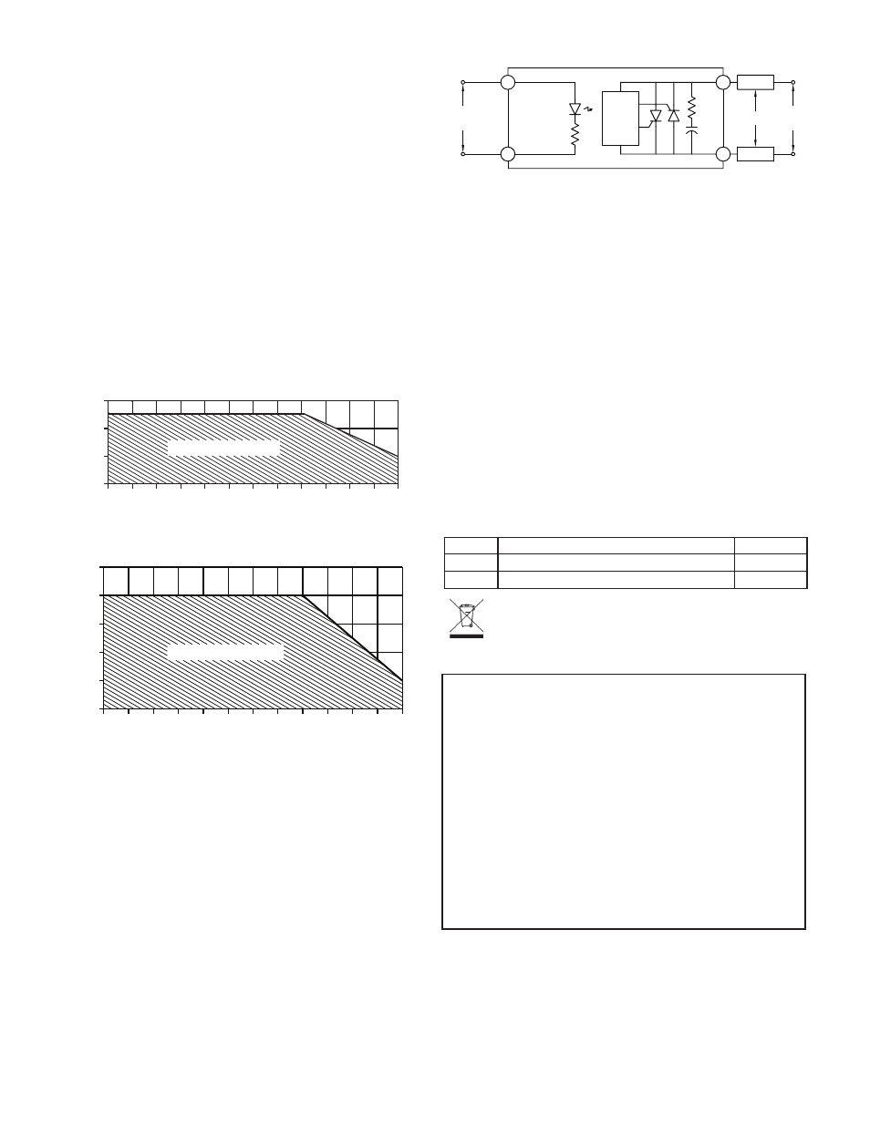
SCHEMATIC
FUSING
Devices such as electromechanical circuit breakers and slow blow fuses
cannot react quickly enough to protect this relay in a shorted condition. Fast
“semiconductor fuses” with appropriate I
2
T ratings are strongly recommended.
MECHANICAL INTERRUPT SWITCH
The off-state leakage current of the power unit is 8 mA maximum. The
voltage level of the output will rise proportional to the resistance of the load due
to this leakage current. Full line voltage can be measured when the output is
connected to a high resistance load and the power unit is in the off-state.
A mechanical interrupt switch is recommended between both sides of the line
voltage and the load. The switch should be opened when servicing any part of
the output wiring. When measuring the off-state output voltage of the unit for
correct operation, load the output of the RLY6/RLY6A with a small resistance
(approximately 100 ohms).
WIRING GUIDELINES
The controlling device and the relay load should NEVER share the same
power feed. It is recommended that this relay be installed as close as possible
to the load to keep the power cable runs short. The control voltage can run over
distances in excess of 200 feet with shielded cable. If using shielded cable,
connect the shield to the minus “-” terminal of the control signal at one end only.
ORDERING INFORMATION
MODEL NO.
DESCRIPTION
PART NUMBERS
RLY6
25 A Single Phase Din Rail Mount Solid State Relay
RLY60000
RLY6A
40 A Single Phase Din Rail Mount Solid State Relay
RLY6A000
3
4
2
1
Zero
voltage
detect
Snubber
+
-
Voltage
Control
Load
Load
A.C.
Line
or
It is strongly recommended that a 0.18" (4.6 mm) clearance is maintained on
all four sides of the relay. If the relays are mounted against each other, then the
end relays must be derated by additional 10% (of the Derating Curve) and the
middle relays by 20%.
In small enclosures, adequate ventilation must be provided to assure proper
safe operating temperature. Accumulation of dust and dirt on the heat sink fins
will also affect heat dissipation. In extreme dust and dirt conditions, the relay
must be derated by additional 20%.
LIMITED WARRANTY
The Company warrants the products it manufactures against defects in materials and
workmanship for a period limited to two years from the date of shipment, provided
the products have been stored, handled, installed, and used under proper conditions.
The Company’s liability under this limited warranty shall extend only to the repair or
replacement of a defective product, at The Company’s option. The Company disclaims
all liability for any affirmation, promise or representation with respect to the products.
The customer agrees to hold Red Lion Controls harmless from, defend, and indemnify
RLC against damages, claims, and expenses arising out of subsequent sales of RLC
products or products containing components manufactured by RLC and based upon
personal injuries, deaths, property damage, lost profits, and other matters which Buyer,
its employees, or sub-contractors are or may be to any extent liable, including without
limitation penalties imposed by the Consumer Product Safety Act (P.L. 92-573) and
liability imposed upon any person pursuant to the Magnuson-Moss Warranty Act (P.L.
93-637), as now in effect or as amended hereafter.
No warranties expressed or implied are created with respect to The Company’s products
except those expressly contained herein. The Customer acknowledges the disclaimers
and limitations contained herein and relies on no other warranties or affirmations.
Red Lion Controls
Headquarters
20 Willow Springs Circle
York PA 17406
Tel +1 (717) 767-6511
Fax +1 (717) 764-0839
Red Lion Controls
China
Unit 302, XinAn Plaza
Building 13, No.99 Tianzhou Road
ShangHai, P.R. China 200223
Tel +86 21 6113 3688
Fax +86 21 6113 3683
Red Lion Controls
Europe
Softwareweg 9
NL - 3821 BN Amersfoort
Tel +31 (0) 334 723 225
Fax +31 (0) 334 893 793
Red Lion Controls
India
201-B, 2nd Floor, Park Centra
Opp 32 Mile Stone, Sector-30
Gurgaon-122002 Haryana, India
Tel +91 984 487 0503
Do not dispose of unit in trash - Recycle