Power wiring, Voltage/resistance/current input signal wiring, Temperature input signal wiring – Red Lion PAX2C User Manual
Page 3: User input wiring
3
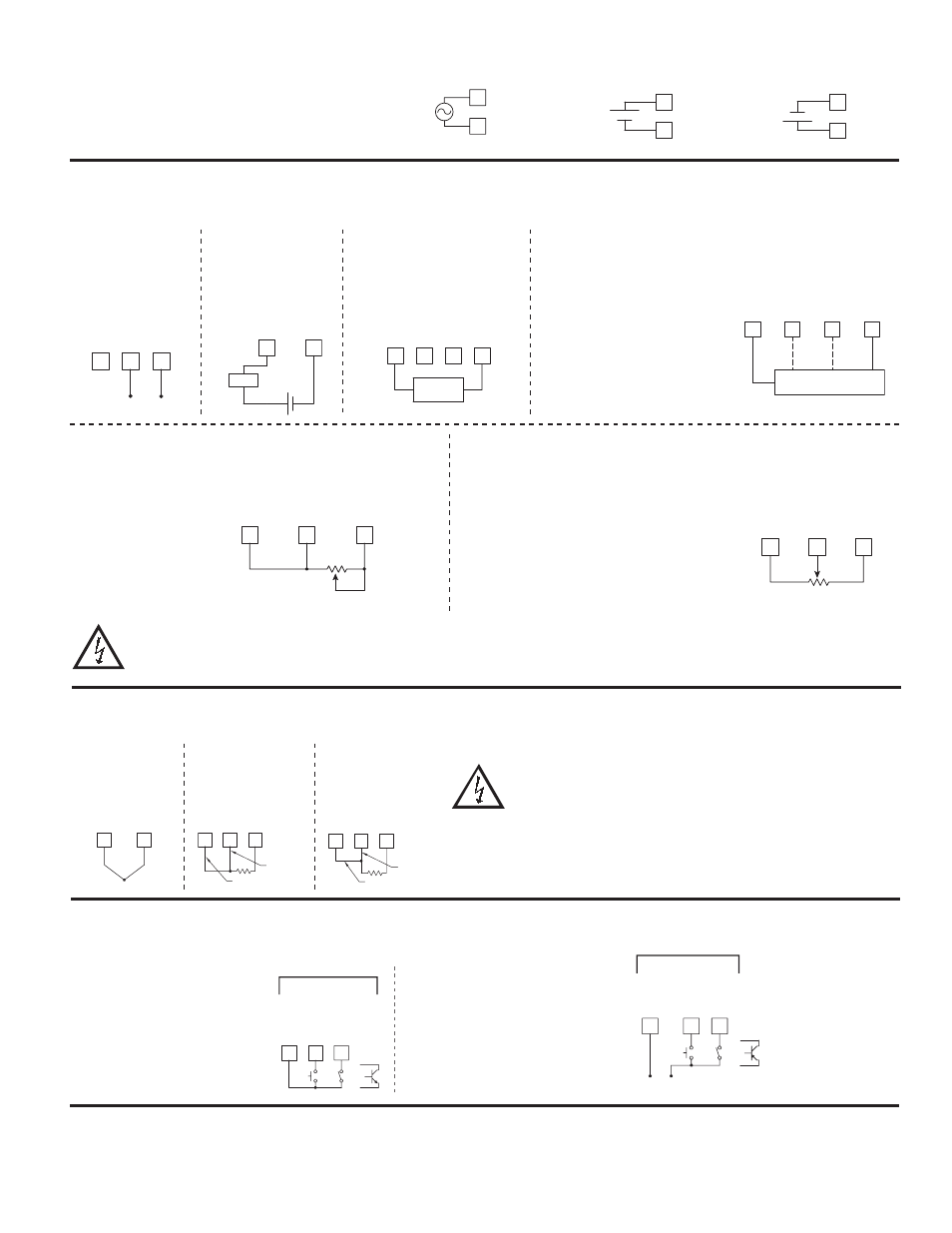
POWER WIRING
The power supplied to the meter shall employ a 15 Amp UL
approved circuit breaker for AC input and a 1 Amp, 250 V UL
approved fuse for DC input. It shall be easily accessible and
marked as a disconnecting device to the installed unit. This device
is not directly intended for connection to the mains without a
reliable means to reduce transient over-voltages to 1500 V.
1
2
AC/DC
AC/DC
VOLTAGE/RESISTANCE/CURRENT INPUT SIGNAL WIRING
IMPORTANT: Before connecting signal wires, the Input Range Jumpers and Excitation Jumper should be verified for proper position.
Process/Current
Signal
(external powered)
Voltage Signal
Process/Current Signal
(2 wire requiring 18V
excitation)
Excitation Jumper: 18 V
6
7
8
+
̶
200VDC MAX.
V-
TC
-R
TD I
N
I INPU
T
INP COMM
Current Signal (3 wire
requiring 18 V excitation)
Terminal 3: +Volt supply
Terminal 6: +ADC (signal)
Terminal 8: -ADC (common)
Excitation Jumper: 18 V
Voltage Signal (3 wire
requiring 18 V excitation)
Terminal 3: +Volt supply
Terminal 7: +VDC (signal)
Terminal 8: -VDC (common)
Excitation Jumper: 18 V
6
8
2A DC MAX.
I INPU
T
INP COMM
Load
-
+
-
+
Resistance Signal
(2 wire requiring excitation)
Terminal 3: Jumper to
terminal 7
Terminal 7: Resistance
Terminal 8: Resistance
Excitation Jumper:
1.05 mA REF.
T/V Jumper: V position
Voltage/Resistance Input Jumper:
Set per input signal
3
7
8
V EX
C
INP COMM
V-TC-RTD-I
N
1.05 mA
REF.
10K MAX
Potentiometer Signal as Voltage Input
(3 wire requiring excitation)
Terminal 3: High end of pot.
Terminal 7: Wiper
Terminal 8: Low end of pot.
Excitation Jumper: 2 V REF.
T/V Jumper: V
Voltage/Resistance Input Jumper: 2 Volt
Module 1 Input Range: 2 Volt
Note: The Apply signal scaling style should be
used because the signal will be in volts.
6
7
8
3
V-TC-RTD-I
N
I INPU
T
V EX
C
INP COMM
+
3 WIRE TRANSMITTER
_
Vout
Iout
3
7
8
Rmin=1KΩ
V EX
C
INP COMM
V-TC-RTD-I
N
2V REF.
2V
INPUT
5
6
3
RT
D EX
C
V EXEC
I INPU
T
2 WIRE
TRANSMITTER
-
+
4
COMM
CAUTION: Sensor input common is NOT isolated from user input common. In order to preserve the safety of the controller application, the sensor input
common must be suitably isolated from hazardous live earth referenced voltages; or input common must be at protective earth ground potential. If not,
hazardous live voltage may be present at the User Inputs and User Input Common terminals. Appropriate considerations must then be given to the
potential of the user input common with respect to earth common; and the common of the isolated plug-in cards with respect to input common.
1
2
AC/DC
AC/DC
+
-
1
2
AC/DC
AC/DC
+
-
OR
AC Power
DC Power
TEMPERATURE INPUT SIGNAL WIRING
IMPORTANT: Before connecting signal wires, verify the T/V Jumper is in the T position.
3-Wire RTD
Thermocouple
2-Wire RTD
5
7
8
RTD EX
C
V-TC-RTD-I
N
INP COMM
Sense Lead
Jumper
5
7
8
RTD EX
C
V-TC-RTD-I
N
INP COMM
Sense Lead
RTD (Excitation)
7
8
+
̶
V-TC-RTD-I
N
INP COMM
CAUTION: Sensor input common is NOT isolated from user input common. In
order to preserve the safety of the controller application, the sensor input
common must be suitably isolated from hazardous live earth referenced
voltages; or input common must be at protective earth ground potential.
If not, hazardous live voltage may be present at the User Inputs and User
Input Common terminals. Appropriate considerations must then be given to
the potential of the user input common with respect to earth common; and
the common of the isolated plug-in cards with respect to input common.
USER INPUT WIRING
If not using User Inputs, then skip this section. User Input terminal does not need to be wired in order to
remain in the inactive state.
Sourcing Logic
(UACt Hi)
When the UACt parameter is programmed
to Hi, the user inputs of the controller are
internally pulled down to 0 V with 20
KW resistance. The input is active when
a voltage greater than 2.2 VDC is
applied.
USER COMM
USER
2
USER
1
10
11
9
USER INPUTS
OR
Sinking Logic
(UACt Lo)
When the UACt parameter is
programmed to Lo, the user inputs
of the controller are internally
pulled up to +3.3 V with 20 KW
resistance. The input is active
when it is pulled low (<1.1 V).
10
9
11
+
-
(30V max.)
SUPPLY
V
USER COM
M
USER
2
USER
1
USER INPUTS
OR
SETPOINT (ALARMS) WIRING
SERIAL COMMUNICATION WIRING
ANALOG OUTPUT WIRING
See appropriate plug-in card
bulletin for wiring details.