Rear terminals, Safety summary, Meter installation – Red Lion PAX2C User Manual
Page 2: Installation environment, Setting the jumpers, Input range jumpers
2
SAFETY SUMMARY
All safety related regulations, local codes and instructions that appear in this
literature or on equipment must be observed to ensure personal safety and to
prevent damage to either the instrument or equipment connected to it. If
equipment is used in a manner not specified by the manufacturer, the protection
provided by the equipment may be impaired. Do not use this unit to directly
command motors, valves, or other actuators not equipped with safeguards. To do
so can be potentially harmful to persons or equipment in the event of a fault to
the unit.
METER INSTALLATION
The PAX2C meets NEMA 4X/IP65 requirements when properly installed.
The unit is intended to be mounted into an enclosed panel. Prepare the panel
cutout to the dimensions shown. Remove the panel latch from the unit. Slide the
panel gasket over the rear of the unit to the back of the bezel. The unit should
be installed fully assembled. Insert the unit into the panel cutout.
While holding the unit in place, push the panel latch over the rear of the unit
so that the tabs of the panel latch engage in the slots on the case. The panel latch
should be engaged in the farthest forward slot possible. To achieve a proper seal,
tighten the latch screws evenly until the unit is snug in the panel (Torque to
approximately 7 in-lbs [79N-cm]). Do not over-tighten the screws.
Installation Environment
The unit should be installed in a location that does not exceed the operating
temperature and provides good air circulation. Placing the unit near devices that
generate excessive heat should be avoided.
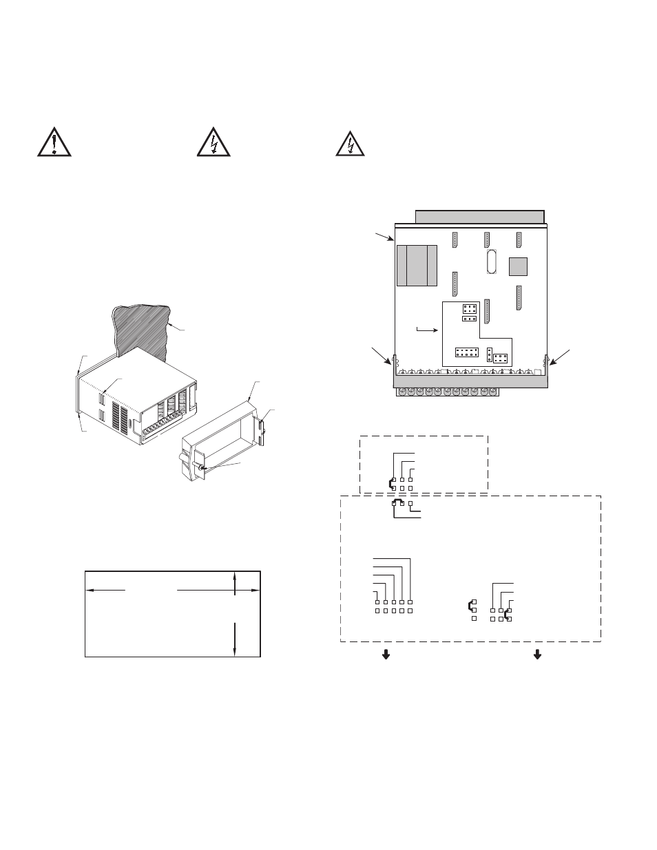
SETTING THE JUMPERS
The PAX2C controller has four jumpers that must be checked and/or changed
prior to applying power. The following Jumper Selection Figures show an
enlargement of the jumper area.
To access the jumpers, remove the controller base from the case by firmly
squeezing and pulling back on the side rear finger tabs. This should lower the
latch below the case slot (which is located just in front of the finger tabs). It is
recommended to release the latch on one side, then start the other side latch.
Warning: Exposed line voltage exists on the circuit boards. Remove all
power to the controller and load circuits before accessing inside of
the controller.
INPUT RANGE JUMPERS
CAUTION: Risk of Danger.
Read complete instructions prior to
installation and operation of the unit.
CAUTION:
Risk of electric shock.
PANEL
LATCHING
SLOTS
BEZEL
PANEL
GASKET
PANEL
LATCH
LATCHING
TABS
PANEL
MOUNTING
SCREWS
-.00
(92 )
-.0
+.8
3.62
+.03
(45 )
1.77
-.0
+.5
-.00
+.02
PANEL CUT-OUT
Main
Circuit
Board
REAR TERMINALS
FRONT DISPLAY
I
T
V
RTD
JUMPER
LOCATIONS
100
Finger
Tab
Finger
Tab
V
EXCITATION OUTPUT JUMPER
INPUT RANGE JUMPERS
18V @ 50mA
2V REF.
1.05 mA REF.
10 ohm RTD
100 ohm RTD
RTD INPUTS
CURRENT INPUTS
2 A
.25 A
.025 A
.0025 A
250 µA
TEMPERATURE
VOLTAGE
THERMOCOUPLE/
VOLTAGE
SELECTION
LV - 250mV/2V/100Ω/1KΩ
M - 10V/100V
HV - 25V/200V/10KΩ
VOLTAGE/RESISTANCE
INPUTS
REAR TERMINALS