General specifications, Block diagram – Red Lion CSDIO User Manual
Page 2
2
GENERAL SPECIFICATIONS
1. POWER: Derived from system backplane. (CSDIO draws 170 mA max. load
on power input of MASTER). Modules may be hot-swapped (replaced while
powered up).
2. LEDs:
STS - Status LED shows module condition.
IN1-IN8 - LEDs are lit when associated input is active.
OP1-OP6 - LEDs are lit when associated output is active.
ALM - Alarm LED is lit when an internal alarm condition exists.
3. MEMORY: Non-volatile memory retains all programmable parameters.
MASTER also stores the parameters in order to reprogram modules that
are replaced.
4. INPUTS: DIP switch selectable for sink or source
Maximum voltage: +30 VDC, reverse polarity protected
Off Voltage: < 1.2 Volts
On Voltage: > 3.8 Volts
Input Impedance: Source Mode 10K ohms; Sink Mode 20K ohms
Input Frequency*:
Filter switch on: 50 Hz
Filter switch off: 300 Hz
* Actual useable frequency limited by communication to external device.
5. OUTPUTS: Outputs available as FORM-A relay or Solid State NFET.
Form A Relay Output:
Type: N.O.
The following pairs of relays share the common terminal: 1&2, 3&4, 5&6
Current Rating by pair: 3 Amps @ 30 VDC / 125 VAC resistive
1/10 HP @ 125 VAC
Life Expectancy: 200,000 cycles at maximum load rating. (Decreasing
load, increasing cycle time, and use of surge suppression such as RC
snubbers increases life expectancy.)
Solid State Output:
Type: Switched DC, N Channel open drain MOSFET
Contact Rating: 1 ADC max
VDS ON: < 0.2 V @ 1 A
VDS MAX: 30 VDC
Offstate Leakage Current: 0.5
A max
6. LOGIC (BOOLEAN) MODE:
Count Frequency: 200 Hz/input when input is directly connected (soft-wired)
to the counter.
Logic Propagation Delay: 400 msecs. max.
Timer Accuracy: 0.2%
7. ISOLATION LEVEL: 500 Vrms @ 50/60 Hz for 1 minute between the
following:
Inputs
Outputs
CS Master Power Supply Input
8. COMMUNICATIONS: Provided by the CS Master
9. ENVIRONMENTAL CONDITIONS:
Operating Temperature Range: 0 to +50 °C
Storage Temperature Range: -40 to +85 °C
Operating and Storage Humidity: 85% max relative humidity, non-
condensing, from 0 to +50 °C
Vibration According to IEC 68-2-6: Operational 10 to 150 Hz, 0.075 mm
amplitude in X, Y, Z direction 1 g.
Shock According to IEC 68-2-27: Operational 25 g (10 g relay), 11 msec in
3 directions.
Altitude: Up to 2000 meters
10. CERTIFICATIONS AND COMPLIANCES:
SAFETY
Check each module’s specifications to determine system compliance.
UL Listed, File # E302106, UL508, CSA C22.2 No. 14-M05; File
#E179259, UL61010-1, CAN/CSA-C22.2 No. 61010-1; and File
#E317425, ANSI/ISA 12.12.01-2007, CSA 22.2 No. 213-M1987
LISTED by Und. Lab. Inc. to U.S. and Canadian safety standards
IEC 61010-1, EN 61010-1: Safety requirements for electrical equipment
for measurement, control, and laboratory use, Part 1.
ELECTROMAGNETIC COMPATIBILITY
Emissions and Immunity to EN 61326: 2006: Electrical Equipment for
Measurement, Control and Laboratory use.
Immunity to Industrial Locations:
Electrostatic discharge
EN 61000-4-2 Criterion B
4kV contact discharge
8kV air discharge
Electromagnetic RF fields
EN 61000-4-3 Criterion A
10V/m (80 MHz to 1 GHz)
3 V/m (1.4 GHz to 2 GHz)
1 V/m (2 GHz to 2.7 GHz)
Fast transients (burst)
EN 61000-4-4 Criterion B
power 2kV
I/O signal 1kV
I/O signal connected to power 2kV
Surge
EN 61000-4-5 Criterion B
power 1 kV L to L, 2 kV L to G
signal 1 kV
RF conducted interference
EN 61000-4-6 Criterion A
3 Vrms
Emissions:
Emissions
EN55011
Class A
Notes:
1. Criterion A: Normal operation within specified limits.
2. Criterion B: Temporary loss of performance from which the unit self-
recovers.
3. Power supplied from back plane via Master Module.
11. CONSTRUCTION: Case body is burgundy high impact plastic. For indoor
use only. Installation Category II, Pollution Degree 2.
12. CONNECTIONS: Removable wire clamp screw terminal blocks.
Wire Gage: 28-16 AWG terminal gage wire
Torque: 1.96-2.23 inch/lbs (0.22-0.25 N-m)
13. MOUNTING: Snaps on to standard DIN style top hat (T) profile mounting
rails according to EN50022 -35 x 7.5 and -35 x 15.
14. WEIGHT: 6.6 oz (187.1 g)
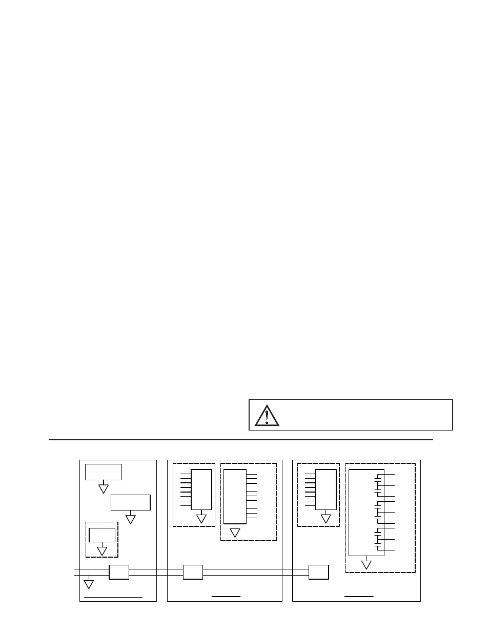
PORT 1
PROGRAMMING
A
COMMUNICATIONS
PORT 2
POWER
SUPPLY
24VDC
+
-
ISOLATED
PORT 3
ETHERNET
CSMSTR - MASTER
INPUTS
ISOLATED
CSDIO14S
1
8
SUPPLY
POWER
OUTPUTS
1
ISOLATED
A
B
C
D
A
NFET
2
COM 1,2
COM 3,4
4
3
COM 5,6
6
5
F
OUTPUTS
RELAY
ISOLATED
5
COM 5,6
6
COM 3,4
3
4
COM
1,2
1
2
8
E
ISOLATED
1
INPUTS
CSDIO14R
POWER
SUPPLY
BLOCK DIAGRAM
WARNING - EXPLOSION HAZARD - DO NOT DISCONNECT
EQUIPMENT UNLESS POWER HAS BEEN SWITCHED OFF OR
AREA IS KNOWN TO BE NON-HAZARDOUS.