Hardware, Installation, Protocol conversion – Red Lion CSMSTRZR User Manual
Page 3: Power supply requirements, Emc installation guidelines, Figure 4 - installation complete, Din rail
3
HARDWARE
INSTALLATION
DIN rail should be mounted horizontally so that the unit’s ventilation holes
are vertical in relation to cabinet orientation. A minimum clearance of 1 inch
(25.4 mm) should be maintained above and below the unit in order to ensure
proper thermal regulation. A minimum top clearance of 3.00 inch is needed
when using the USB/PG port.
The unit shall be installed inside a UL Listed Industrial Control Panel or
similar type of enclosure. A minimum 3.2 mm distance shall be maintained
between the hazardous live parts of the equipment and accessible parts of the
fire/electrical enclosure.
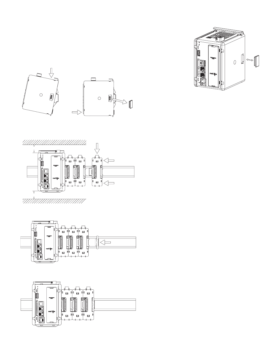
Figure 1 - Attach Master To DIN Rail and Remove Rubber
End Cap
Figure 2 - Attach Slave Bases To DIN Rail
Figure 3 - Attach Termination Plug*
* Supplied with Master.
Figure 4 - Installation Complete
PROTOCOL CONVERSION
Mount the Master as shown under Hardware Installation Figure 1. Install the
rubber end cap. The end cap protects
the pins from damage. Configure
the Master for zero modules.
POWER SUPPLY REQUIREMENTS
It is very important that the power supply is mounted correctly if the unit is
to operate reliably. Please take care to observe the following points:
– The power supply must be mounted close to the unit, with usually not more
than 6 feet (1.8 m) of cable between the supply and the master. Ideally, the
shortest length possible should be used.
– The wire used to connect the Master’s power supply should be at least
22-gage wire. If a longer cable run is used, a heavier gage wire should be
used. The routing of the cable should be kept away from large contactors,
inverters, and other devices which may generate significant electrical noise.
– A power supply with an NEC Class 2 or Limited Power Source (LPS) and
SELV rating is to be used. This type of power supply provides isolation to
accessible circuits from hazardous voltage levels generated by a mains
power supply due to single faults. SELV is an acronym for “safety extra-
low voltage.” Safety extra-low voltage circuits shall exhibit voltages safe
to touch both under normal operating conditions and after a single fault,
such as a breakdown of a layer of basic insulation or after the failure of a
single component has occurred.
Visit www.redlion.net for a complete list of our PSDR Series of NEC Class 2
power supplies.
EMC INSTALLATION GUIDELINES
Although Red Lion Controls Products are designed with a high degree of
immunity to Electromagnetic Interference (EMI), proper installation and wiring
methods must be followed to ensure compatibility in each application. The type
of the electrical noise, source or coupling method into a unit may be different
for various installations. Cable length, routing, and shield termination are very
important and can mean the difference between a successful or troublesome
installation. Listed are some EMI guidelines for a successful installation in an
industrial environment.
1. A unit should be mounted in a metal enclosure, which is properly connected
to protective earth.
2. Use shielded cables for all Signal and Control inputs. The shield connection
should be made as short as possible. The connection point for the shield
depends somewhat upon the application. Listed below are the recommended
methods of connecting the shield, in order of their effectiveness.
a. Connect the shield to earth ground (protective earth) at one end where the
unit is mounted.
b. Connect the shield to earth ground at both ends of the cable, usually when
the noise source frequency is over 1 MHz.
3. Never run Signal or Control cables in the same conduit or raceway with AC
power lines, conductors, feeding motors, solenoids, SCR controls, and
heaters, etc. The cables should be run through metal conduit that is properly
grounded. This is especially useful in applications where cable runs are long
and portable two-way radios are used in close proximity or if the installation
is near a commercial radio transmitter. Also, Signal or Control cables within
an enclosure should be routed as far away as possible from contactors,
control relays, transformers, and other noisy components.
4. Long cable runs are more susceptible to EMI pickup than short cable runs.
5. In extremely high EMI environments, the use of external EMI suppression
devices such as Ferrite Suppression Cores for signal and control cables is
effective. The following EMI suppression devices (or equivalent) are
recommended:
Fair-Rite part number 0443167251 (RLC part number FCOR0000)
Line Filters for input power cables:
Schaffner # FN2010-1/07 (Red Lion Controls # LFIL0000)
1
2
REMOVE
DIN RAIL
4
DEPRESS
3
4
1.00" min. clearance; 3.00" when using USB/PG port.
TOP
1.00" min. clearance
BOTTOM
STS
CF
ETHERNET
RS48
5
RS232
USB HOST
RS232/PG
DIN RAIL
5
STS
CF
ETHERNE
T
RS485
RS232
USB HOST
RS232/PG
DIN RAIL
STS
CF
ETHERNET
RS48
5
RS23
2
USB HOST
RS232/PG