0 assembling the display, Removing the mpax module, Installing the option cards – Red Lion LPAX/MPAX User Manual
Page 3: Installing the mpax, Installing the labels
CAUTION: The MPAX main circuit board and the option cards
contain static sensitive components. Before handling the module
or the cards, discharge static charges from your body by
touching a grounded bare metal object. Handle the module by
the rear plastic cover only, and the option cards by the board
edges. Dirt, oil or other contaminants that contact the circuit
boards or components can adversely affect circuit operation.
WARNING: Exposed line voltage exists on the MPAX main circuit
board and the option cards. DO NOT apply power to the
module OR load circuits until the module is properly installed
in the LPAX case.
NOTE: All module and option card labels must be installed as
shown for safety purposes.
3
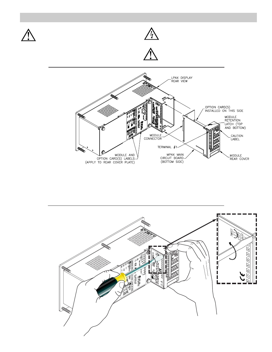
Removing The MPAX Module
To remove the MPAX Module from the LPAX Display, first
remove all power and load circuits. Then insert a flat
screwdriver blade (
3
/
16
" or
1
/
4
") into the narrow slot
between the LPAX rear cover plate and the
module’s plastic cover as illustrated in Figure
2. Twist the screwdriver in the direction
shown to disengage the internal
connectors while firmly
squeezing and pulling back
on the rear finger tabs
(top and bottom).
Carefully slide the
module out of the
LPAX case, keeping it
properly aligned with
the case opening.
1.0 ASSEMBLING THE DISPLAY
Prior to installing the LPAX Display, it is recommended that the MPAX
and any option cards be assembled first. This will allow you the
opportunity to insure all the boards are fitted properly into their
connectors.
Installing the Option Cards
If your application requires option
cards, they should be installed into the
MPAX before it is installed into the
LPAX Display. Refer to the
literature enclosed with the option
cards for installation instruction.
Installing the MPAX
To install the MPAX Module,
align the module with the opening
in the LPAX case, as illustrated.
The module must be oriented as
shown, with terminal #1 toward the
top of the LPAX case. Carefully
slide the module into the LPAX case.
The LPAX and MPAX connectors will begin
to engage about
¼"
from the bottom. At this point,
apply a small amount of pressure to the rear of the
MPAX module to fully engage the connection. Be sure the
module fully snaps into the slots at the rear of the LPAX case. The
display is ready for installation.
Installing the Labels
Each option card and the MPAX are shipped with a connection label. These
labels must be applied to the rear of the LPAX in the positions shown in the
drawing.
Figure 1, Installing an MPAX Module and Option Cards
Figure 2, Removing an MPAX Module