Installation, Selecting location, Electrical connections – Vaisala HMM213 User Manual
Page 19: Figure 2, To help you install this product, Chapter 4
Chapter 4 _______________________________________________________________ Installation
CHAPTER 4
INSTALLATION
This chapter provides you with information that is intended to help you
install this product.
Selecting Location
Finding a suitable site for HMM213 is important for getting
representative ambient measurements
Select a place that gives a true picture of the environment or process and
is as clean as possible. Air should flow freely around the sensor head.
Install the sensor head to a sufficient distance from the duct or chamber
walls. Make sure to insert enough cable to the same space with the probe
in order to prevent heat conduction. If an additional temperature probe is
used, install it so that the warmed sensor head does not interfere with the
measurement.
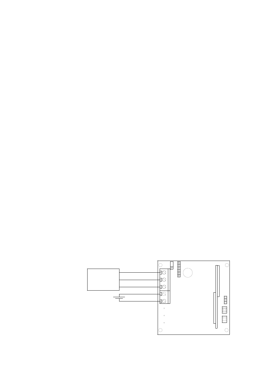
Electrical Connections
The HMM213 module is connected to a process control system with
screw terminals. The wiring diagram is shown in Figure 2 below.
X1
12-35VDC
Us
GND
+
TX
GND
RX
Terminal
TX
RX
GND
Figure 2
Electrical Connections
VAISALA _______________________________________________________________________ 19