Installation, Case 2, Parent unit child‐1 unit – State 520 User Manual
Page 29: Page, If you connect the, 1] (or [2]), Connector of the “parent” unit to the, Parent (or [1])
Installation
29
│
Page
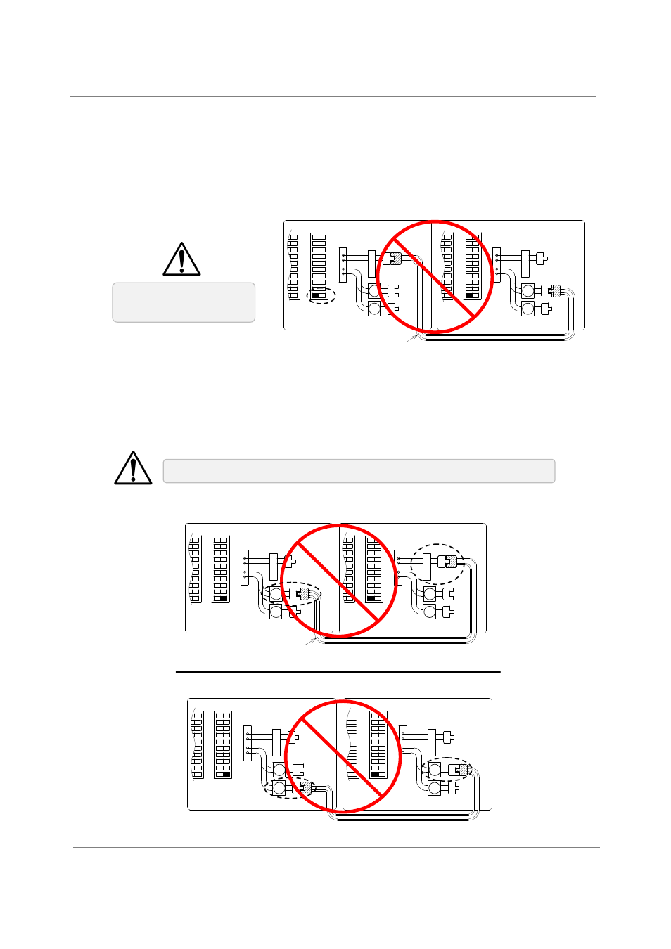
CASE 1:
Unless you change dipswitch No.10 of the “PARENT” unit to the “ON” position, the system
will not work as an Easy‐Link system. The units will operate as individual units.
CASE 2:
If you connect the
“
[1] (or [2])
”
connector of the “PARENT” unit to the
“
PARENT (or [1])
”
connector of the “CHILD‐1” unit, the system will not work as an Easy‐link system. The units will
operate as individual units.
Wrong dipswitch setting
on the “PARENT” unit
Wrong connection between the “PARENT” unit and the “CHILD‐1” unit
(C) Examples of incorrect settings and/or connections
C o n n e c t o r s
P
A
R
E
N
T
2
1
2
1
C o n n e c t o r s
P
A
R
E
N
T
2
1
2
1
C o m m u n i c a t i o n c a b l e
O
F
F
O
N
1
2
3
4
5
6
7
8
Righ t ban k
of D ipswi tch e s
O
F
F
O
N
9
1
0
1
2
3
4
5
6
7
8
1
2
3
4
5
6
7
8
9
1
0
O
F
F
O
N
1
2
3
4
5
6
7
8
Righ t ba nk
of D i psw itche s
O
F
F
O
N
9
1
0
1
2
3
4
5
6
7
8
1
2
3
4
5
6
7
8
9
1
0
PARENT unit
CHILD‐1 unit
C o n n e c t o r s
P
A
R
E
N
T
2
1
2
1
C o n n e c t o r s
P
A
R
E
N
T
2
1
2
1
C o m m u n i c a t i o n c a b l e
O
F
F
O
N
1
2
3
4
5
6
7
8
R ight b an k
o f Dip s wi tche s
O
F
F
O
N
9
1
0
1
2
3
4
5
6
7
8
1
2
3
4
5
6
7
8
9
1
0
O
F
F
O
N
1
2
3
4
5
6
7
8
R ight ba n k
o f Dip sw i tche s
O
F
F
O
N
9
1
0
1
2
3
4
5
6
7
8
1
2
3
4
5
6
7
8
9
1
0
PARENT unit
CHILD‐1 unit
C o n n e c t o r s
P
A
R
E
N
T
2
1
2
1
C o n n e c t o r s
P
A
R
E
N
T
2
1
2
1
O
F
F
O
N
1
2
3
4
5
6
7
8
R igh t ba n k
o f D ipsw i tc hes
O
F
F
O
N
9
1
0
1
2
3
4
5
6
7
8
1
2
3
4
5
6
7
8
9
1
0
O
F
F
O
N
1
2
3
4
5
6
7
8
R i ght bank
o f Dip swit che s
O
F
F
O
N
9
1
0
1
2
3
4
5
6
7
8
1
2
3
4
5
6
7
8
9
1
0
PARENT unit
CHILD‐1 unit