Installation, Child‐3 unit parent unit child‐1 unit child‐2 unit, Page – State 520 User Manual
Page 28: 3 digit 7‐seg. led
Installation
28
│
Page
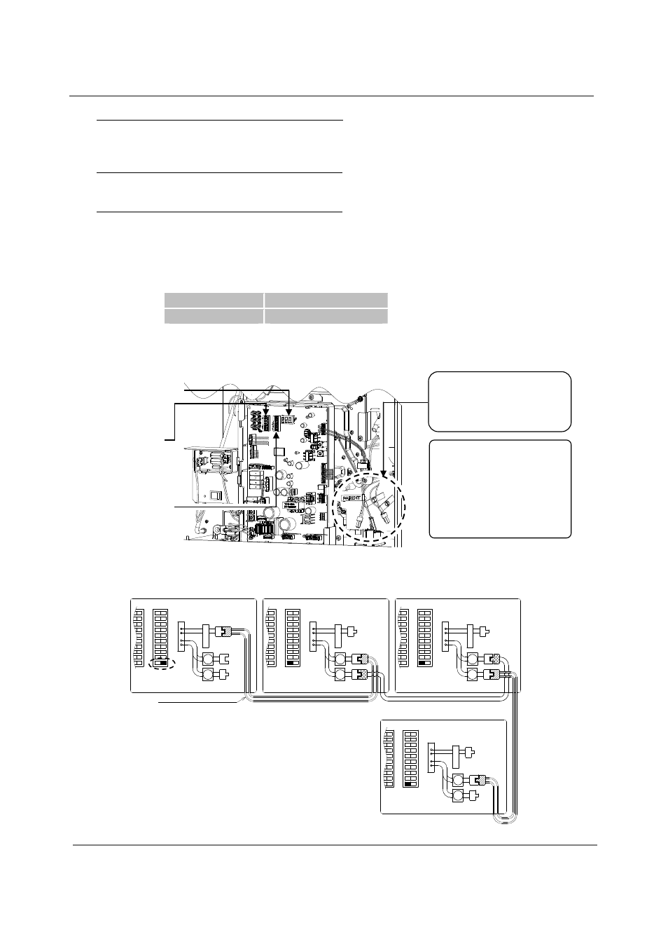
The dark squares indicate the direction
the dipswitches should be set to.
4. Between the “PARENT” and the “CHILD‐1” units
Connect the “PARENT connector” of the “PARENT” unit to the “[1] connector” of the “CHILD‐1”
unit.
5. Between the “CHILD‐1” and the “CHILD‐2” units
Connect the “[2] connector” of the “CHILD‐1” unit to the “[1] connector” of the “CHILD‐2” unit.
6. Between the “CHILD‐2” and the “CHILD‐3” units
Connect the “[2] connector” of the “CHILD‐2” unit to the “[1] connector” of the “CHILD‐3” unit.
7. Make sure the “3‐digit 7‐seg. LED” of all the units’ computer boards display the unit #. The
numbering system automatically allocates the unit # to each water heater in the Easy‐Link system,
in accordance with the table below.
Parent unit
Unit # : 1
Child units
Unit # : 2, 3 and 4
(A) 520 (T‐H2) Computer board
(B) Basic diagram of connections among the 520 (T‐H2) models.
Right bank of
dipswitches
Left bank of
dipswitches
When setting a unit to a
“PARENT” unit, adjust
dipswitch No.10 on the
right bank of
dipswitches only
(see diagram).
Easy‐Link connectors
are next to the
computer board.
3 digit 7‐Seg. LED
CHILD‐3 unit
PARENT unit
CHILD‐1 unit
CHILD‐2 unit
C o n n e c t o r s
P
A
R
E
N
T
2
1
2
1
C o m m u n i c a t i o n c a b l e
C o n n e c t o r s
P
A
R
E
N
T
2
1
2
1
O
F
F
O
N
1
2
3
4
5
6
7
8
Ri g ht ba nk
of Di p sw it c he s
O
F
F
O
N
9
1
0
C o n n e c t o r s
P
A
R
E
N
T
2
1
2
1
C o n n e c t o r s
P
A
R
E
N
T
2
1
2
1
1
2
3
4
5
6
7
8
1
2
3
4
5
6
7
8
9
1
0
O
F
F
O
N
1
2
3
4
5
6
7
8
R i gh t b a n k
o f D ip s w i tc h es
O
F
F
O
N
9
1
0
1
2
3
4
5
6
7
8
1
2
3
4
5
6
7
8
9
1
0
O
F
F
O
N
1
2
3
4
5
6
7
8
R ig ht ba nk
o f Di p sw it c he s
O
F
F
O
N
9
1
0
1
2
3
4
5
6
7
8
1
2
3
4
5
6
7
8
9
1
0
O
F
F
O
N
1
2
3
4
5
6
7
8
R ig h t ba n k
o f D ip sw i tc he s
O
F
F
O
N
9
1
0
1
2
3
4
5
6
7
8
1
2
3
4
5
6
7
8
9
1
0