State 520 User Manual
Page 2
Contents
2
│
Page
NOTE
Check the rating plate to ensure this product matches your
specifications.
In accordance with ANZI Z21.10.3, CO emission does not
exceed 400 PPM for normal input.
CONTENTS
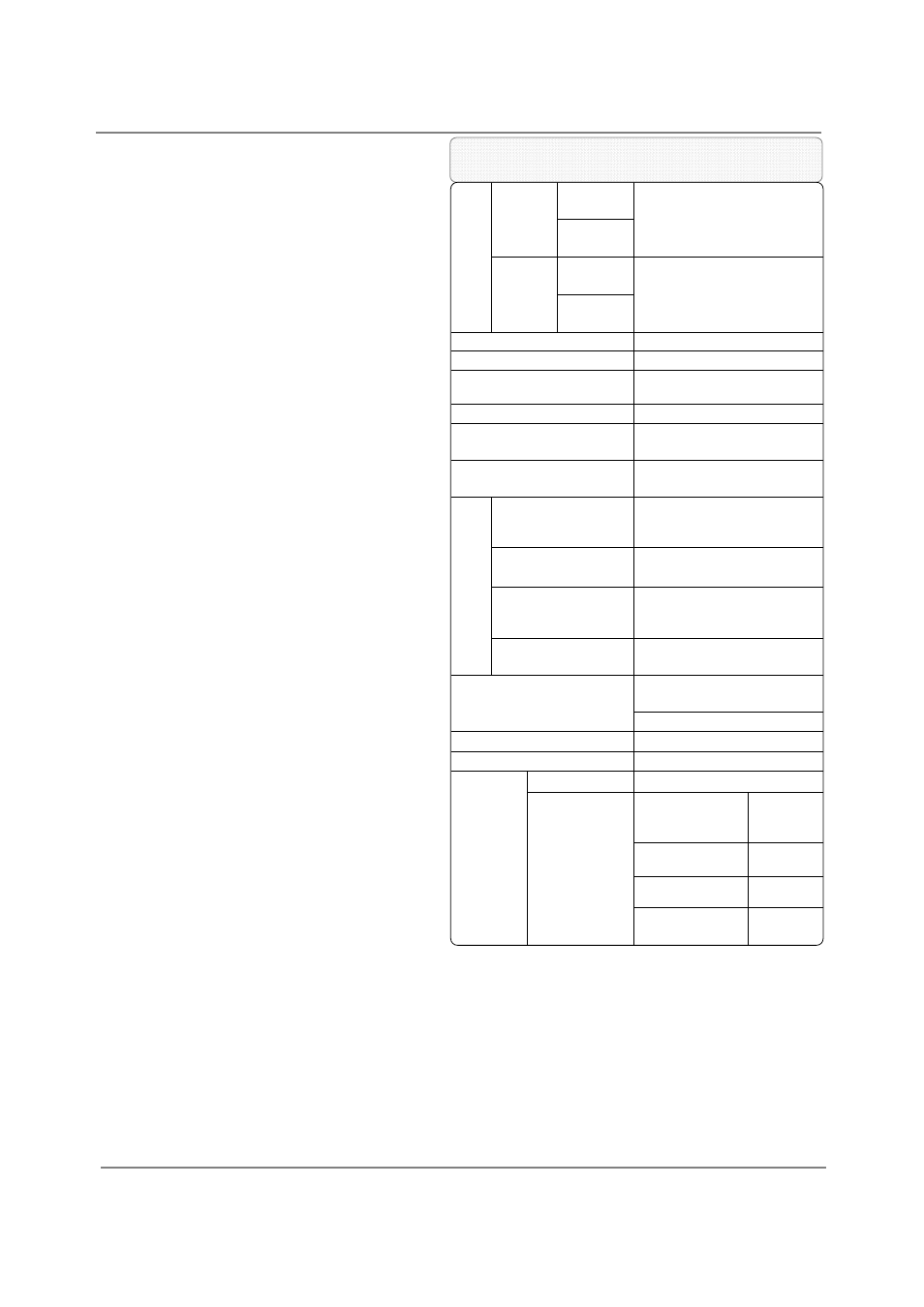
SPECIFICATIONS
520 (T‐H2) and 320 (T‐H2S) models
Gas
Input
520
(T‐H2)
models
Natural
Min: 13,000 Btu/h
Max: 199,000 Btu/h
Propane
320
(T‐H2S)
models
Natural
Min: 13,000 Btu/h
Max: 180,000 Btu/h
Propane
Gas Connection
¾” NPT
Water Connections
¾” NPT
Condensate Drain Port
Connection
½
” NPT
Water Pressure*
15 ‐ 150 psi
Natural Gas
Inlet Pressure
Min. 5.0” WC
Max. 10.5” WC
Propane
Inlet Pressure
Min. 8.0” WC
Max. 14.0” WC
Manif
o
ld
Pressure**
520 Direct
Vent Indoor
(T‐H2‐DV)
Natural: 3.2” WC
Propane: 5.5” WC
520 Outdoor
(T‐H2‐OS)
Natural: 2.7” WC
Propane: 4.6” WC
320 Direct
Vent Indoor
(T‐H2S‐DV)
Natural: 2.5” WC
Propane: 4.3” WC
320 Outdoor
(T‐H2S‐OS)
Natural: 1.9” WC
Propane: 3.6” WC
Weight
73 lbs.
(Direct Vent Indoor models)
71 lbs. (Outdoor models)
Dimensions
H25.6” x W18.5” x D12.4”
Ignition
Electric Ignition
Electric
Supply
120 VAC / 60 Hz
Consumption
Operation of the
Direct Vent
Indoor models
152 W
(1.27A)
Operation of the
Outdoor models
102W
(0.85A)
Standby
8.2 W
(0.07A)
Freeze‐
Protection
207 W
(1.73A)
SPECIFICATIONS………………………………...
INTRODUCTION……………………………….…
SAFETY GUIDELINES…………….……………..
INSTALLATION………………………………..….
General………………………………………..…
Included Accessories…………………..…
Optional items…………………………..…..
Warning for Installations………..….....
High‐altitude Installations………………
Installation for outdoor models……..
Installation for direct vent indoor
models……………………………………………
Venting Instructions……………………....
Gas Supply / Gas Pipe Sizing………...…
Water Connections……………..……….…
Pressure Relief Valve………………………
Condensate drain…………………………..
Electrical Connections…………….........
Remote Controller Connection…….…
Pump Control Connections………..……
Pump Control Mode…………………….…
Easy‐Link System…………………………....
APPLICATIONS...…………………………………
Space Heating……….………….……………
INITIAL OPERATION..…………………….……
OPERATING SAFETY……………………………
NORMAL OPERATION…………………………
General………..……….………….……………
Temperature settings.…….…..…………
Flow……………………………………………….
Freeze Protection System…….…………
Maintenance and Service………………
Unit Draining and Filter Cleaning……
TROUBLESHOOTING……..……………………
General………..……….………….……………
Error codes.…………………….…..…………
COMPONENTS DIAGRAM………………..…
PARTS LIST………………….………………………
OUTPUT TEMPERATURE CHART……...…
LIMITED WARRANTY…………………….……
2
3
4
5
6
6
7
8
9
9
10
10
17
19
20
20
22
23
24
25
27
31
31
33
34
36
36
36
38
38
39
39
40
40
42
44
47
50
51
The manufacturer reserves the right to discontinue, or change at
any time, specifications or designs without notice and without
incurring obligations.
Installation Manual
Owner’s Guide
*40 psi or above is recommended for maximum flow.
**The Manifold Pressure is the factory setting and generally
should not need adjustment.