Installing the new water heater (cont’d) – State PR6 40 NHDST2 User Manual
Page 19
Installing the New Water Heater (cont’d)
19
“Fuel” Conversion Instructions
From Natural Gas To Propane
(L.P.) Gas
Read and follow detailed conversion instructions located on
the water heater and also in this manual in their entirety be-
fore starting the conversion.
Conversion kit with necessary parts are in a bag attached to
the drain valve.
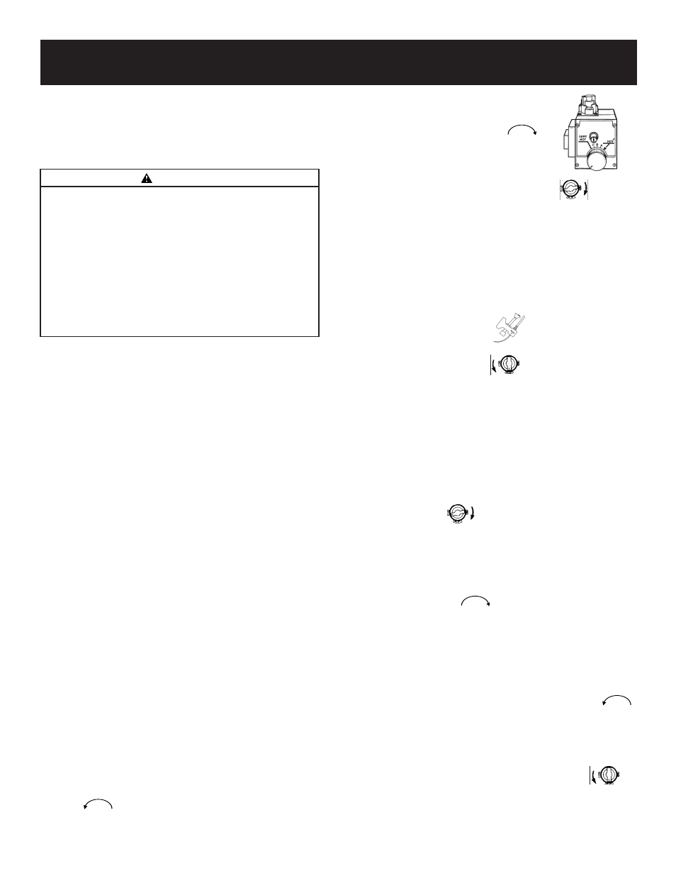
Step 1. Turn gas control knob “A” to “PILOT”. Depress and
turn “OFF”. (See Figure 9, page 20).
Step 2. Remove outer access door from water heater.
Step 3. Remove burner assembly from water heater control
by first removing 6 screws holding inner door to
heater, then loosening
3
⁄
4
″ nut “H” holding burner as-
sembly to control. (See Figures 10a and 10b, page
20). Loosen pilot tube nut “J” and thermocouple nut
“K” at control.
Step 4. Remove screws “D” disengaging manifold from
burner. (See Figure 11, page 20)
Step 5. Remove orifice “E” (See Figure 11, page 20) using
3
⁄
8
″ wrench. Install orifice marked ″L.P.″ found in the
bag into manifold. Tighten securely. Secure burner
to manifold with screws “D”.
Step 6. Loosen pilot tube nut “F” (See Figure 12, page 20).
Remove orifice “G” and replace with red colored
orifice found in bag. Reinstall nut “F” and tighten
securely.
Step 7. Make sure all connections are tightened securely,
and reinstall burner assembly into water heater. Po-
sition end of the manifold inside bracket as shown in
Figure 11 on page 20. Reinstall manifold into control
and tighten
3
⁄
4
inch nut (“H”) securely. Recheck to see
that end of manifold is still inside bracket as shown
in Figure 11 on page 20. Reinstall pilot tubing and
thermocouple into control. (See Figure 10a, page
20). Reinstall inner door using the 6 screws re-
moved in step 3.
Step 8. Place screwdriver in slot “B”. (See Figure 9,
page 20). Depress and turn counter-clockwise
(
) to stop. Control screw must be in “IN” po-
sition for propane (L.P.) gas and in “OUT” position
for natural gas. STOP! Read label “For Your Safety”
located on your water heater.
Step 9. Set the thermostat to lowest set-
ting by turning the water temper-
ature dial clockwise, (
) to
its lowest temperature setting
(with arrow on dial) as shown.
DO NOT FORCE.
Step 10. Turn gas control knob clockwise
to “OFF”
position. Knob cannot be turned from “PILOT” to
“OFF” unless knob is depressed slightly. DO NOT
FORCE.
Step 11. Wait five (5) minutes to clear out any gas. If you
then smell gas, STOP! Follow “B” in the safety in-
formation on “For Your Safety” label. If you don’t
smell gas, go to the next step.
Step 12. Open pilot door. The pilot is located in front of the
burner. (See Figure 12, page 20)
Step 13. If you don’t smell gas, turn knob on gas control
counter-clockwise
to “PILOT” position.
Step 14. Push in control knob all the way and hold down.
Immediately light the pilot through pilot light hole
with a match held by a match holder wire. Con-
tinue to hold control knob in for about one (1)
minute after the pilot is lit. Release knob and it will
pop back up. Pilot should remain lit. If it goes out,
repeat steps 9 through 12.
•
If knob does not pop up when released, stop
and immediately call the gas supplier.
•
If the pilot will not stay lit after several tries,
depress and turn the gas control knob clock-
wise
to “OFF”and call the gas supplier.
Step 15. Check for gas leaks with only pilot flame burning
using a soapy water solution, not a match or open
flame. Check for gas leaks at fittings “F”and “G”
(See Figure 12, page 20) and at fitting “J” (See Fig-
ure 10a, page 20).
Step 16. Make sure temperature adjustment dial is turned
clockwise (
) in its lowest position (See
Figure 9, page 20).
Step 17. Close pilot door. WARNING: Pilot door must be
closed and securely fastened before turning gas
control knob to “ON” position. Replace outer door.
Step 18. At arms length away turn gas control knob to the
full “ON” position. WARNING: Do not use gas
control knob to regulate gas flow. Turn tempera-
ture adjustment dial counter-clockwise (
)
until gas flows to main burner and ignites.
Step 19. With a soapy water solution, not a match or open
flame, check for gas leaks at gas connection “H”.
(See Figure 10a, page 20). If gas leak occurs, turn
off immediately by shutting off gas cock at inlet to
control, or by turning gas control knob to
“PILOT” pushing down and turning to “OFF”. Re-
pair gas leak as necessary, and repeat steps 9
through 19.
(continued on page 20)
THERMOCOUPLE
PILOT BURNER
WARNING
This water heater has been factory equipped to operate with
the type gas indicated in the “EQUIPPED FOR” area of the
model rating plate located near the gas control valve. The
indicated gas may be either Natural or Propane (L.P.). By fol-
lowing the conversion instructions in this manual or the
instructions near the gas control valve, the water heater must
be converted if it is to be used with the opposite gas. DO
NOT USE THIS WATER HEATER WITH ANY GAS OTHER
THAN THE ONE LISTED ON THE MODEL RATING PLATE.
Failure to use the correct gas can cause problems which can
result in DEATH, SERIOUS BODILY INJURY, OR PROPERTY
DAMAGE. If you have any questions or doubts consult your
gas supplier or gas company.