Installing the new water heater (cont’d), Roof jack installation – State PR6 40 NHDST2 User Manual
Page 11
11
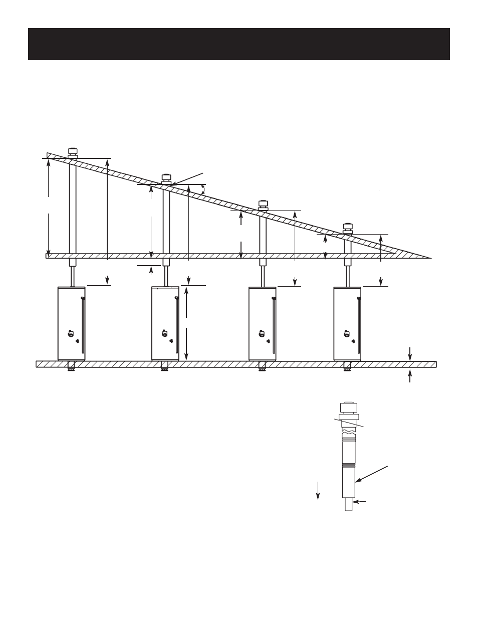
Installing the New Water Heater (cont’d)
4. Ease the roof jack assembly through the roof and ceil-
ing openings. The roof jack flashing tilts up to 22.6°
degrees for use on a sloping roof.
FLUE PIPE
TELESCOPE
OUTER PIPE
AND
FLUE PIPE
DOWN
OUTER PIPE
1. Cut 5
1
⁄
2
″ diameter holes through the roof and ceiling
directly in line with the flue connection on top of the
water heater. For a sloped roof, the roof hole may have
to be enlarged to allow the roof jack to be installed
vertically.
2. Telescope down the flue pipe in the roof jack assembly
to a length that will project at least 6
″ below the fin-
ished ceiling before installing the roof jack assembly.
NOTE: Flue pipe joints have silicone seals that must
remain in place. A soapy water solution sprayed around
the seal area will enable the flue pipe and outer pipe
below to telescope more freely.
3. Telescope down the outer pipe of the roof jack assem-
bly to a length that will project at least 2
″ below the
finished ceiling before installing the roof jack assem-
bly.
Roof Jack Installation
Roof Jack Kit Models VENT KIT / 12 IN. (9002964), VENT KIT / 32 IN. (9002965),
VENT KIT / 60 IN. (9002966), and VENT KIT / 95 IN. (9002967)
VENT KIT / 95 IN.
VENT KIT / 60 IN.
Adj. 0-22.6°
MAX. PITCH 5-12
VENT KIT / 32 IN.
VENT KIT / 12 IN.
96
″″ MAX.
49
″″ MIN.
136
″ MAX.
55
″ MIN.
100
″ MAX.
40
″ MIN.
72
″ MAX.
25
″ MIN.
32
″ MAX.
17
″ MIN.
52
″ MAX.
18
″ MIN.
12
″ MAX.
2
″ MIN.
23
″ MAX.
56
″
22.6
″
60
″ MAX.
32
″ MIN.