Locating the new water heater (cont’d) – State GS6 65 XRRT User Manual
Page 8
Combustion Air and Ventilation
for Appliances Located in
Unconfined Spaces
Unconfined Space is a space whose volume is not less than 50
cubic feet per 1,000 Btu per hour of the aggregate input rating
of all appliances installed in that space. Rooms communicating
directly with the space in which the appliances are installed,
through openings not furnished with doors, are considered a
part of the unconfined space
In unconfined spaces in buildings, infiltration may be adequate
to provide air for combustion, ventilation and dilution of flue
gases. However, in buildings of tight construction (for example,
weather stripping, heavily insulated, caulked, vapor barrier,
etc.), additional air may need to be provided using the methods
described in Combustion Air and Ventilation for Appliances
Located in Confined Spaces.
Combustion Air and Ventilation
for Appliances Located in
Confined Spaces
Confined Space is a space whose volume is less than 50 cubic
feet per 1,000 Btu per hour of the aggregate input rating of all
appliances installed in that space.
a. ALL AIR FROM INSIDE BUILDINGS:
(See Page 7 Figure 1, and Figure 2 below)
The confined space shall be provided with two permanent
openings communicating directly with an additional room(s)
of sufficient volume so that the combined volume of all
spaces meets the criteria for an unconfined space. The total
input of all gas utilization equipment installed in the com-
bined space shall be considered in making this determina-
tion. Each opening shall have a minimum free area of one
square inch per 1,000 Btu per hour of the total input rating
of all gas utilization equipment in the confined space, but
not less than 100 square inches. One opening shall com-
mence within 12 inches of the top and one commencing
within 12 inches of the bottom of the enclosure.
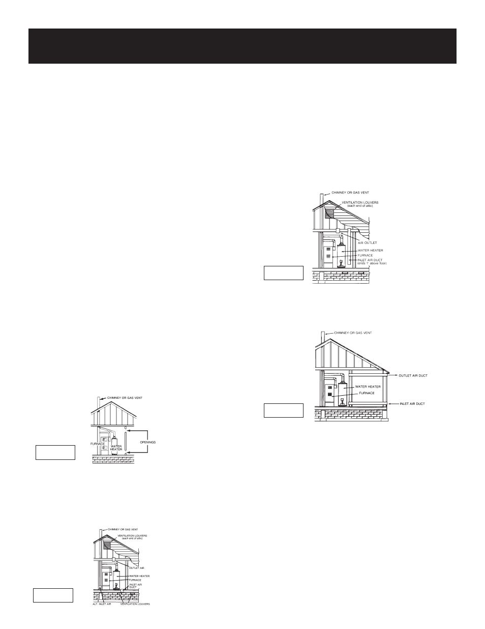
b. ALL AIR FROM OUTDOORS: (see Figures 3-5)
The confined space shall be provided with two permanent
openings, one commencing within 12 inches of the top
and one commencing within 12 inches from the bottom
of the enclosure. The openings shall communicate direct-
ly, or by ducts, with the outdoors or spaces (crawl or attic)
that freely communicate with the outdoors.
1. When directly communicating with the outdoors, each
opening shall have a minimum free area of 1 square inch
per 4,000 Btu per hour of total input rating of all equip-
ment in the enclosure. (See Figure 3.)
2. When communicating with the outdoors through vertical
ducts, each opening shall have a minimum free area of 1
square inch per 4,000 Btu per hour of total input rating of
all equipment in the enclosure. (See Figure 4.)
3. When communicating with the outdoors through horizon-
tal ducts, each opening shall have a minimum free area of
1 square inch per 2,000 Btu per hour of total input rating
of all equipment in the enclosure. (See Figure 5.)
4. When ducts are used, they shall be of the same cross-sec-
tional area as the free area of the openings to which they
connect. The minimum short side dimension of rectangu-
lar air ducts shall not be less than 3 inches. (See Figure 5.)
5. Louvers and Grilles: In calculating free area, consideration
shall be given to the blocking effect of louvers, grilles or
screens protecting openings. Screens used shall not be
smaller than
1
⁄
4
inch mesh. If the free area through a design
of louver or grille is known, it should be used in calculat-
ing the size opening required to provide the free area
specified. If the design and free area is not known, it may
be assumed that wood louvers will be 20-25 percent free
area and metal louvers and grilles will have 60-75 percent
free area. Louvers and grilles shall be fixed in the open
position or interlocked with the equipment so that they are
opened automatically during equipment operation.
6. Special Conditions Created by Mechanical Exhausting or
Fireplaces: Operation of exhaust fans, ventilation systems,
clothes dryers or fireplaces may create conditions requir-
ing special attention to avoid unsatisfactory operation of
installed gas utilization equipment.
Locating the New Water Heater (cont’d)
Figure 2
Figure 4
Figure 5
Figure 3
8