Maintenance instructions – A.R.I. D040C EN User Manual
Page 3
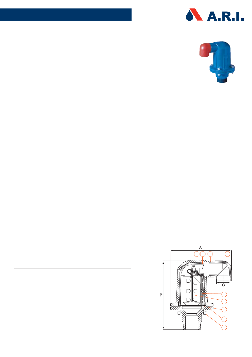
COMBINATION AIR VALVE
BARAK, MODEL D-040-C 2”
GENERAL INSTRUCTIONS
- Routine service is an integral part of the standard procedure for maintenance of a
water supply system.
- Recommended routine maintenance– once or twice a year, according to the quality
and type of the fluids in the system.
PROCEDURE
1. Close the service valve under the valve base before servicing.
2. Loosen and remove the four bolts and nuts (9).
3. Remove the metal shell (2) and enclosed valve body (1).
4. Remove the clamping stem (5) from the valve body (1) and carefully pull out the
float (6) with the attached rolling seal assembly (3).
5. Check the soundness of the rolling seal assembly (3) by washing it with water
and examining it. Note: Replace the seal assembly (3) in case it is torn.
6. Wash the body (1) and the float (6) with clean water and examine for
damage. Note: Replace the float (6) if it is damaged.
7. Clean the drainage elbow (4) to remove insects and debris.
8. Return the float (6) with the attached rolling seal assembly (3) to its original
position in the valve body (1) and lock them into place with the clamping stem (5).
9. Place the metal shell (2) and enclosed valve body (1) on the base (8).
Note: First make sure the O-ring (7) is seated properly in the base of the valve (8).
10. Attach by inserting and tightening the four bolts and nuts (9).
11. Remember to open the service valve after the servicing.
PARTS SPECIFICATION
NO.
DESCRIPTION
MATERIAL
1.
Metal Shell
Cast Iron
2.
Valve Body
Reinforced Nylon
3.
Rolling Seal Assembly
4.
Drainage Elbow
Polypropylene
5.
Clamping Stem
Reinforced Nylon
6.
Float
Foamed Polypropylene
7.
O-Ring
BUNA-N
8.
Base
Brass
9.
Bolt & Nut
Cast Iron
MAINTENANCE INSTRUCTIONS
5
4
3 2
1
6
7
8
9