Connections, Figure 4, Hdsl2 edge connector wiring – ADTRAN HDSL2 User Manual
Page 18
Connections
HDSL2 for General Distribution Installation and Maintenance Practice
8
61223HDSL2L2-5B
CONNECTIONS
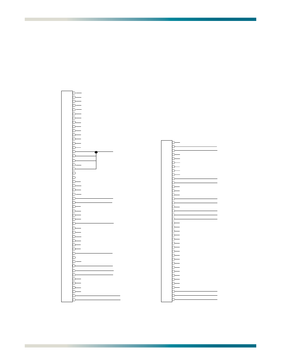
An H2TU-C module occupies one card slot in the respective Office Repeater Bay for which it is
named. Power and alarm signals are provided to the module through the backplane of the
shelf. DSX-1 and HDSL2 loop signals are connected to the wire-wrap pins or mass termi-
nation (amphenol) shelf connectors corresponding to the slot the module occupies.
specify the edge connection wiring required for proper
operation.
Figure 4. HDSL2 Edge Connector Wiring
1
2
3
4
5
6
7
8
9
10
11
12
13
14
15
16
17
18
19
20
21
22
23
24
25
26
27
28
29
30
31
32
33
34
35
36
37
38
39
40
41
42
43
44
45
46
47
48
49
50
-48 VDC RET
HDSL2 Tip (Wire-Wrap)
HDSL2 Ring (Wire-Wrap)
-48 VDC (1)
DSX-1 Rx In Tip (Wire-Wrap) Input to H2TU-C
DSX-1 Rx In Ring (Wire-Wrap) Input to H2TU-C
-48 VDC RET
DSX-1 Tx Out Tip (Wire-Wrap) Output from H2TU-C
DSX-1 Tx Out Ring (Wire-Wrap) Output from H2TU-C
Fuse Alarm
220 Edge
Connector Wiring
100
101
102
103
104
105
106
107
108
109
110
111
112
113
114
115
116
117
118
119
200
201
202
203
204
205
206
207
208
209
210
211
212
213
214
215
216
217
218
219
HDSL2 Tip
HDSL2 Ring
DSX-1 Rx Tip
DSX-1 Rx Ring
DSX-1 Tx Tip
DSX-1 Tx Ring
Fuse Alarm (to Alarm Module)
-48 VDC Return
Frame Ground
-48 VDC
-48 VDC Return
-48 VDC Return
DDM+ Edge
Connector Wiring