Terminals and ports, Installation – Outback Power Systems GFX International Series Installation Manual User Manual
Page 19
Installation
900-0111-01-00 Rev B
17
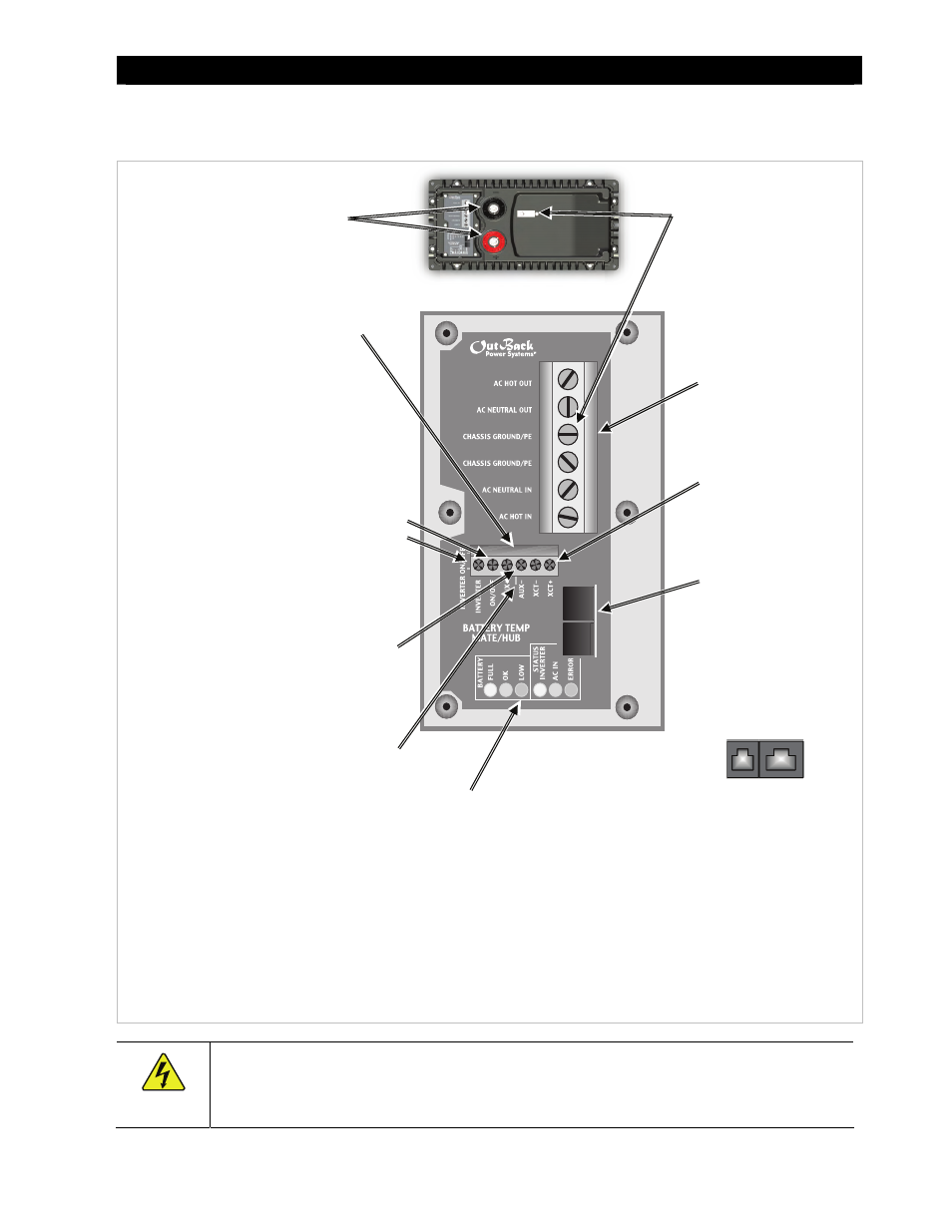
Terminals and Ports
Figure 5
Terminals, Ports, and Features
WARNING: Shock Hazard
The inverter’s AC output is defaulted to ON from the factory. It will deliver 230 Vac as soon as DC power is
connected.
INVERTER ON/OFF: Connects wires for a manual
on/off switch to control the inverter. The jumper
alongside (JP1) disables these terminals when
installed (factory default). In this state, the inverter is
always ON and can only be controlled by the system
display. See page 23 for instructions.
DC TERMINALS: Connect to battery
cables and DC system. See page 19 for
instructions.
DC and AC GROUND
TERMINALS: Connect to
grounding system for both
batteries and AC. See page 18
for instructions.
CONTROL WIRING TERMINAL BLOCK:
Connects control wires for a variety of
functions, including automatic generator
starting. See pages 24 and 25 for
instructions and the International Series GFX
Operator’s Manual for more information.
The Terminal Block can be unplugged from the
AC board for convenience. While installed,
keep screws tight and the block itself secured
tightly to the AC board to prevent malfunction.
XCT+/XCT- :
Non-operational
terminals. Do not
connect anything
to them.
MATE and RTS PORTS:
Connect the RJ45 and
RJ11 plugs from the
system display and
Remote Temp Sensor. See
page 23 for instructions.
The jacks are mounted
sideways. When viewed
from the left side, they
appear as shown below.
AC TERMINAL BLOCK:
Connects AC input and
output wires. See page 21
for instructions.
LED INDICATORS: Display the unit status and battery voltage. The
Operator’s Manual contains extensive descriptions of the LED functions.
¾ The three BATTERY LEDs (green, yellow, and red) are based on DC
voltage, and provide a very general idea of battery state.
¾ The green INVERTER LED tells if the inverting function is on.
¾ The yellow AC IN LED tells if an AC source is present.
¾ The red ERROR LED indicates either a Warning or an Error. A Warning
is an alert for a problem that is not severe enough for shutdown. An
Error usually accompanies inverter shutdown. See the Operator’s
Manual for more information.
AUX OUTPUT (AUX+/AUX-): Delivers 12 Vdc up
to 0.7 amps (8.4 watts). The output can be
switched on and off for many functions. The
default function is to drive a cooling fan. See page
24 for details. See the system display manual for
programming instructions.
AUX LED INDICATOR: Amber LED turns on when
12 Vdc output is present.