Warning messages, Troubleshooting – Outback Power Systems GFX Series Inverter/Charger Operators Manual User Manual
Page 39
Troubleshooting
900-0114-01-00 Rev A
37
Warning Messages
A Warning message is caused by a non-critical fault. When this occurs, the unit will not shut down, but
the ERROR LED (see page 11) will flash to show a condition that requires attention. See the system
display manual for instructions on viewing warnings. One or more messages will display yes. If a
message says no, it is not the cause of the warning.
Some warnings can become Errors if left unattended. Frequency and voltage warnings are meant to
warn of a problematic AC source. Often the inverter will disconnect from the source. This will occur if
the condition lasts longer than the inverter’s transfer delay settings. If the inverter disconnects, the
warning will display as long as the source is present, accompanied by a Disconnect message. (See
next page.)
Warning screens can only display warnings; they cannot clear them. The way to correct the fault may
be obvious from the message.
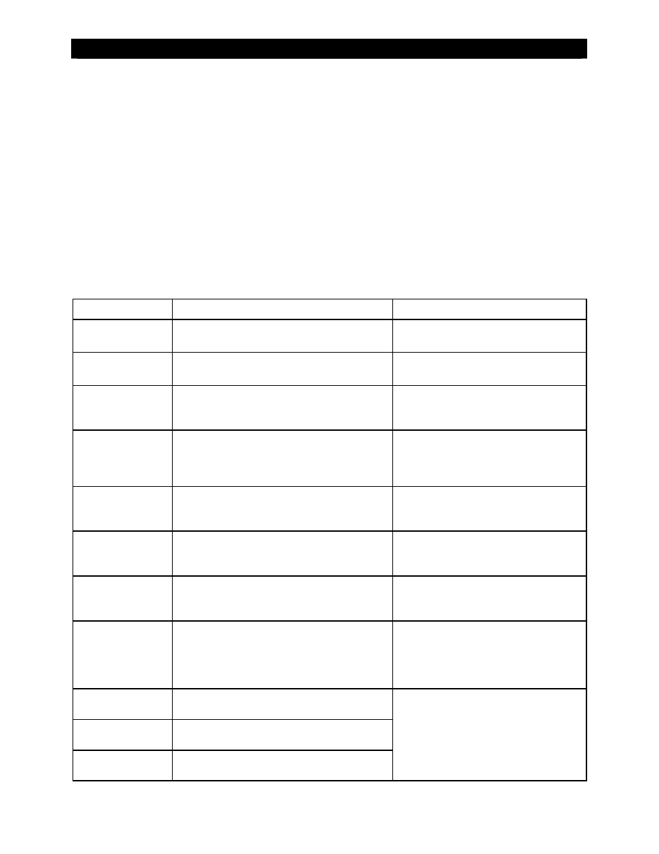
Table 6 Warning Troubleshooting
Message Definition
Possible
Remedy
acin freq too high
The AC source is above the upper acceptable
frequency limit (66 Hz) and prevents connection.
Check the AC source. If it is a generator,
reduce its speed.
acin freq too low
The AC source is below the lower acceptable
frequency limit (54 Hz) and prevents connection.
Check the AC source. If it is a generator,
increase its speed.
acin voltage too high
The AC source is above the upper acceptable
voltage limit (132 Vac default setting) and prevents
connection.
Check the AC source. The inverter’s range is
adjustable. However, this will accommodate
an AC problem, not fix it.
acin voltage too low
The AC source is below the lower acceptable
voltage limit (108 Vac default setting) and prevents
connection.
Check the AC source. Check the AC wiring.
The inverter’s acceptance range is
adjustable. However, this will accommodate
an AC problem, not fix it.
acin input current
exceeds max
AC loads are drawing more current from the AC
source than allowed by the input setting.
Check the loads. Oversized loads can trip the
input breaker. If they exceed the inverter’s
transfer relay size, the relay can be damaged.
temperature sensor
fault
An internal inverter temperature sensor may be
malfunctioning. This is indicated by an unusual
airtemp, fettemp, or captemp reading.
Check sensor readings (see below). The
numeric values represent electronic counts
between 0 and 255.1
internal comm error
detected
Probable failure on inverter’s control board.
Despite the name, this is not an inverter-defined
error and is not accompanied by a shutdown.
Unit may require repair. Contact OutBack
Technical Support (see inside front cover of
this manual).
internal fan failure
detected
The inverter’s internal cooling fan is not operating
properly. Lack of cooling may result in derated
inverter output wattage.
Turn the battery disconnect off, and then on,
to determine if the fan self-tests, then
contact OutBack Technical Support for the
next step. Meanwhile, run the inverter at
reasonable levels or apply external cooling.
airtemp1
Displays a code representing the air temperature
within the inverter.
fettemp1
Displays a code representing the temperature of
the FETs (Field Effect Transistors) and heat sink.
captemp1
Displays a code representing the temperature of
the inverter’s ripple capacitors.
Lower counts stand for higher temperatures,
and higher counts mean lower temperatures.
Room temperature is 210 – 220. The internal
fan runs at 142, and stops at 164. A count of
either 0 or 255 is a defective sensor. Contact
OutBack Technical Support if necessary (see
inside front cover of this manual).
1These values are in digital counts, not degrees. The values are used for troubleshooting purposes.