Thunderbird rack & pinion system – Flaming River Thunderbird Rack & Pinion Cradle Kits 1955-57 User Manual
Page 5
Thunderbird Rack & Pinion System
Page 4 of 13
Flaming River Ind. 800-648-8022
Modified on 02/06/08
JJ/RD/BC
Color Verification to be completed before disassembly
Before disconnecting the turn signal connector, verify the wiring color to ensure proper operation, the use
of a wiring diagram is recommended.
• Brake Light Switch
:
• RR Turn Signal
:
• LR
Turn
Signal
:
• Turn Signal Power :
• Hazard Power :
• RF Turn Signal :
• LF Turn Signal :
• Horn :
Original Steering System Removal
5 Disconnect your battery.
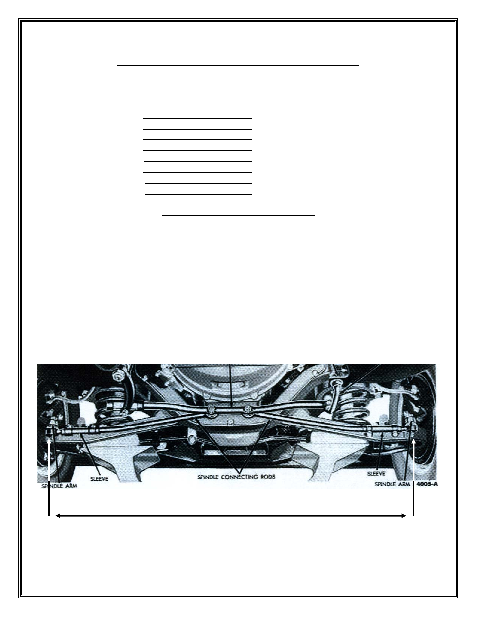
5 Before disassembly measure from zirc to zirc on the outer tie rod ends. Mark this dimension on
page 5 in step 3.
5 Disconnect the wiring at the bottom of the steering gear housing and the steering column.
5 Remove the horn ring from the steering wheel, and then remove the upper steering column, upper
steering shaft, and steering wheel as an assembly from the car.
5 Loosen the lower steering column clamp, and then remove the two screws from the upper steering
column bracket.
5 Remove the sector shaft arm nut, then using a pitman arm puller remove the arm from the
steering box.
5 Remove the bolts that hold the steering gear to the frame and remove the box from the car.
5 Remove the bolts that hold the idler arm bracket to the frame and the outer tie rod ends from the
spindle arms, and then remove the steering linkage from the car.
Before disassembly measure from zirc to zirc on the outer tie rod ends