Flaming River Galaxie Rack & Pinion Cradle Kit 1962-64 User Manual
Page 6
Page 5 of 8
01262010
rd/jj
Aftermarket Wheel Installation Con’t
4)
Tighten the adapter-retaining nut until the adapter is approximately 1/16” away from the column shroud.
Connecting Electrical System
Caution: Before disconnecting your original steering column wiring harness please verify each wire color and function
on the worksheet below. Some wire colors may vary from year to year.
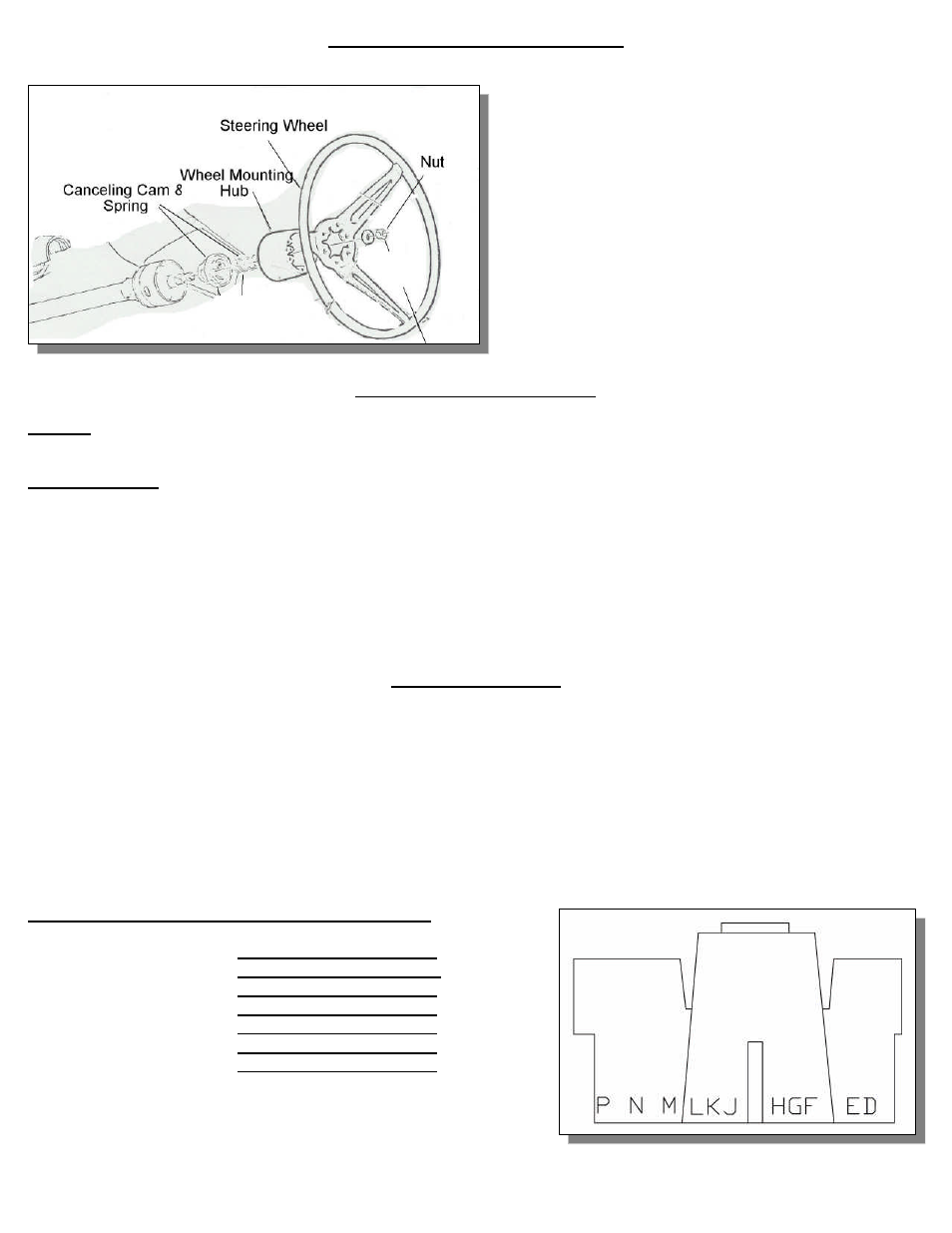
COLUMN WIRING
P -
WHITE
– BRAKE LIGHT SWITCH
N -
DK GREEN
- RR TURN SIGNAL
M –
YELLOW
– L TURN SIGNAL
L –
PURPLE
– TUR SIGNAL POWER
K –
BROWN
- HAZARD POWER
J-
DK BLUE
- RF TURN SIGNAL
H-
LT BLUE
- LF TURN SIGNAL
G-BLACK HORN
Installing Horn Relay
The yellow wire from the vehicle connects to TERMINAL 30 (yellow wire) on the horn relay; the blue wire with the yellow stripe
connects to TERMINAL 87 (Red Wire) on the horn relay. The black wire from the column connects to TERMINAL 85 (brown wire)
on the horn relay. Run a jumper wire from TERMINAL 86 (blue wire) to TERMINAL 30 on the horn relay.
NOTE: FOR 1964-½ MUSTANGS, HORN RELAY IS NOT REQUIRED FOR THIS APPLICATION; VEHICLE HAS A RELAY
FROM THE FACTORY. BLACK WIRE FROM COLUMN WILL BE CONNECTED TO BLUE w/YELLOW STRIPE TO COMPLETE
THE GROUND CIRCUIT.
HAZARD NOTE: FROM 1964 ½ TO 1966 VEHICLES DID NOT HAVE HAZARDS, SO NO HAZARD POWER WIRE IS
PRESENT BUT CANBE ADDED BY PURCHASING
PART # FR20118-1
Color Verification to be completed before disassembly
Brake Light Switch:
RR Turn Signal:
LR Turn Signal:
Turn Signal Power:
Hazard Power:
RF Turn Signal:
LF Turn Signal:
Horn: