Quick Fuel Technology 4500 Alcohol Conversion Kit User Manual
Page 2
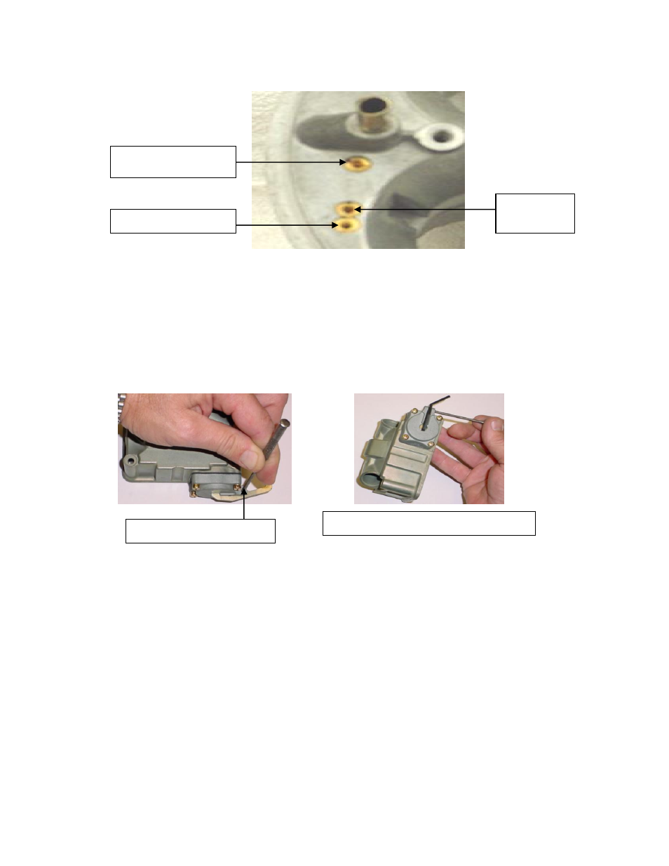
carburetor install the BLANK bleed. In the boss right next to it, moving toward the center, install the
air bleed marked with the number 40. In the boss next to the accelerator pump discharge nozzle insert
the air bleed marked with the number 25. Repeat this same sequence in the remaining throttle bores.
7. Remove the two pump discharge nozzles (squirters) and stainless screws. In the small parts bag find
the two thick composite gaskets, two thin paper gaskets. Place the composite gasket on the accelerator
pump nozzle hole in the main body, slip the paper gasket over the nozzle screw, then the nozzle
(squirter) and install as a unit on top of the composite gasket, center on the locator tab and tighten with
an 5/32” Allen wrench. The main body portion is now complete
8. Place the fuel bowl so the opening is facing down on your workbench. With a small punch drive the
roll pin that retains the operating arm out of the accelerator pump housing. Install the bent pump arm
supplied with the angled section facing away or pointing down. Tap in the original roll pin with a
small punch until the roll pin is just about flush with the housing. Repeat the process on the second
bowl.
9. While the fuel bowl is still facing down on the workbench remove the old needle and seat assembly.
Hold the adjustment nut with a 5/8” wrench, with a large blade screwdriver loosen the lock screw
while holding the nut. Remove the needle and seat assembly. Set this assembly aside temporarily.
10. Turn the fuel bowl over. With a medium common tip screwdriver, remove the two screws holding in
the float assembly. Remove the entire assembly. Do both fuel bowls at the same time.
11. Lay both floats down on the workbench the same way it came out of the float bowl, with the hinge on
top. Remove the float hinge by pulling it through both the float bracket, float hinge and spring.
12. Reassemble using the new float. Place the float on the workbench in the same orientation as the bowl,
place the hinge on top of the float, and align the holes. Place the small end of the spring in the float
hinge locator hole. Slide the float hinge through the bracket and hinge holes as well as the float spring.
Once all the way through the assembly take the long end of the spring and position it in the cutout in
the float hinge. Use the other float assembly as a guide if needed. Repeat, using the first assembly as a
reference if needed.
13. Install the float assembly into each bowl. Insert the original screws and tighten. Note; these are self-
tapping screws so do not over-tighten.
14. Remove the adjusting nut and lock screw from the needle and seat assemblies. Locate the appropriate
gaskets in the small parts bag. Thread in the new needle and seat assembly into the fuel bow. When
the resistance makes it difficult, turn the fuel bowl upside down, place the large gasket on top of the
adjusting nut, slip the gasket and nut over the notch in the needle and seat assembly. Turn the nut
clockwise until the straight edge of the float is even with the center of the float bracket retainer screws.
With the float bowl still inverted, use a 3/8” drill bit, adjust the needle and seat until the drill just fits
Install blank air bleed here
Install #40 here
this is the idle
air bleed.
Insert #25 bleed here, this is
the high speed bleed.
Remove roll pin with small punch
Reinstall roll pin with new pump arm as shown.