Merit Medical Fountain 5 French with Squirt User Manual
Page 5
I
N S T R U C T I O N S
F O R
U
S E
F
LUSHING AND
D
EBUBBLING THE
S
YSTEM
1. Flush the Fountain Infusion Catheter with ster-
ile, heparinized normal saline so that all the air
has been completely removed.
W
ARNING
: Complications may occur if all the air
has not been removed prior to insertion into the
body.
2. Place the Fountain Infusion Catheter into posi-
tion under fluoroscopic guidance following stan-
dard hospital protocol. The Fountain Infusion
Catheter will pass through a standard 5F
introducer sheath and over a 0.035" (0.89 mm)
guide wire. The two radiopaque marker bands
on the Fountain Infusion Catheter indicate the
infusion segment where side hole infusion
occurs. (See Figure 1)
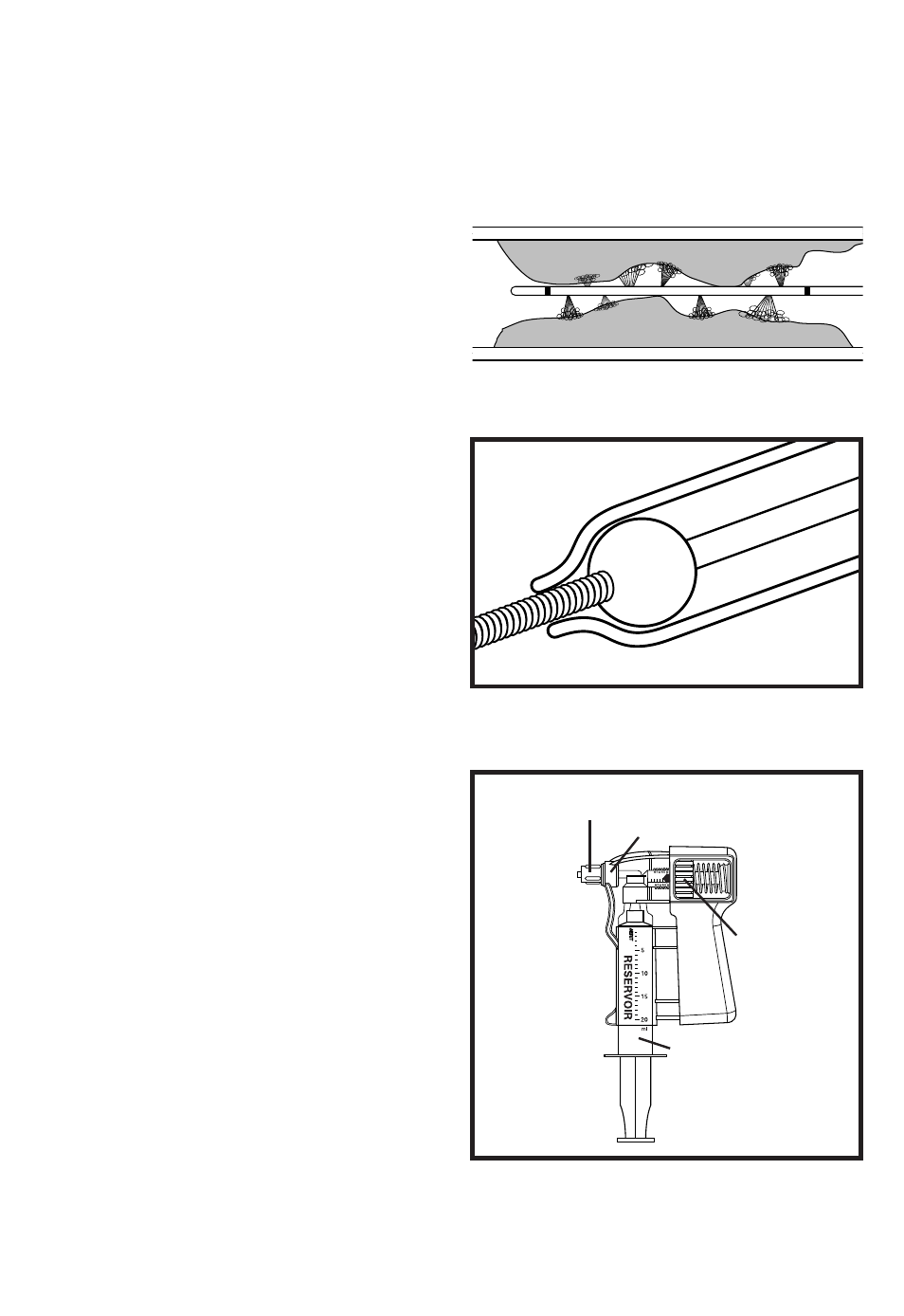
3. Remove the 0.035" placing guide wire and
position the Occluding Wire so that the distal tip
of the catheter is occluded by the guide wire.
(See Figure 2)
W
ARNING
: A guide wire should never be
advanced or removed if resistance is present. If
the guide wire is advanced against resistance, it
could potentially create vessel trauma and/or
wire damage. The cause of the resistance should
be determined under fluoroscopy. Take any nec-
essary actions to correct the problem.
4. The 20ml reservoir syringe is filled with
heparinized saline and debubbled using standard
hospital protocol. This may include tapping the
syringe with a hemostat or similar device.
Attach reservoir syringe to Squirt. (See Figure 3)
Make sure that the syringe connection is air-tight.
[The syringe rotator should be tightened by hand
if using a syringe with a rotating adapter.]
Holding the Squirt in an upright position activate
the trigger bar repeatedly until all air bubbles are
out of the check valve area of the Squirt. (See
Figure 3) This may include tapping the Squirt
fluid path with a hemostat or similar device.
[Note: Clinician should attach a small piece of
tubing if concerned about fluid dripping out of
the end of the Squirt during the priming process.]
Figure 1
Figure 2
Figure 3
E-3
SHERLOCK CONNECTOR
CHECK VALVE
KNURLED
ADJUSTING
KNOB
RESERVOIR SYRINGE
TRIGGER
BAR