Irx-rx port: connection and wiring – AMX NetLinx Integrated Controllers NI-700/900 User Manual
Page 23
Connections and Wiring
19
NI-700 & NI-900 Hardware Reference Guide
The table below provides information about the connector pins, signal types, and signal functions.
This table’s wiring specifications are applicable to the rear RS-232/422/485 Device Port connectors on
the: NI-700 (Ports 1 & 2) and NI-900 (Port 1).
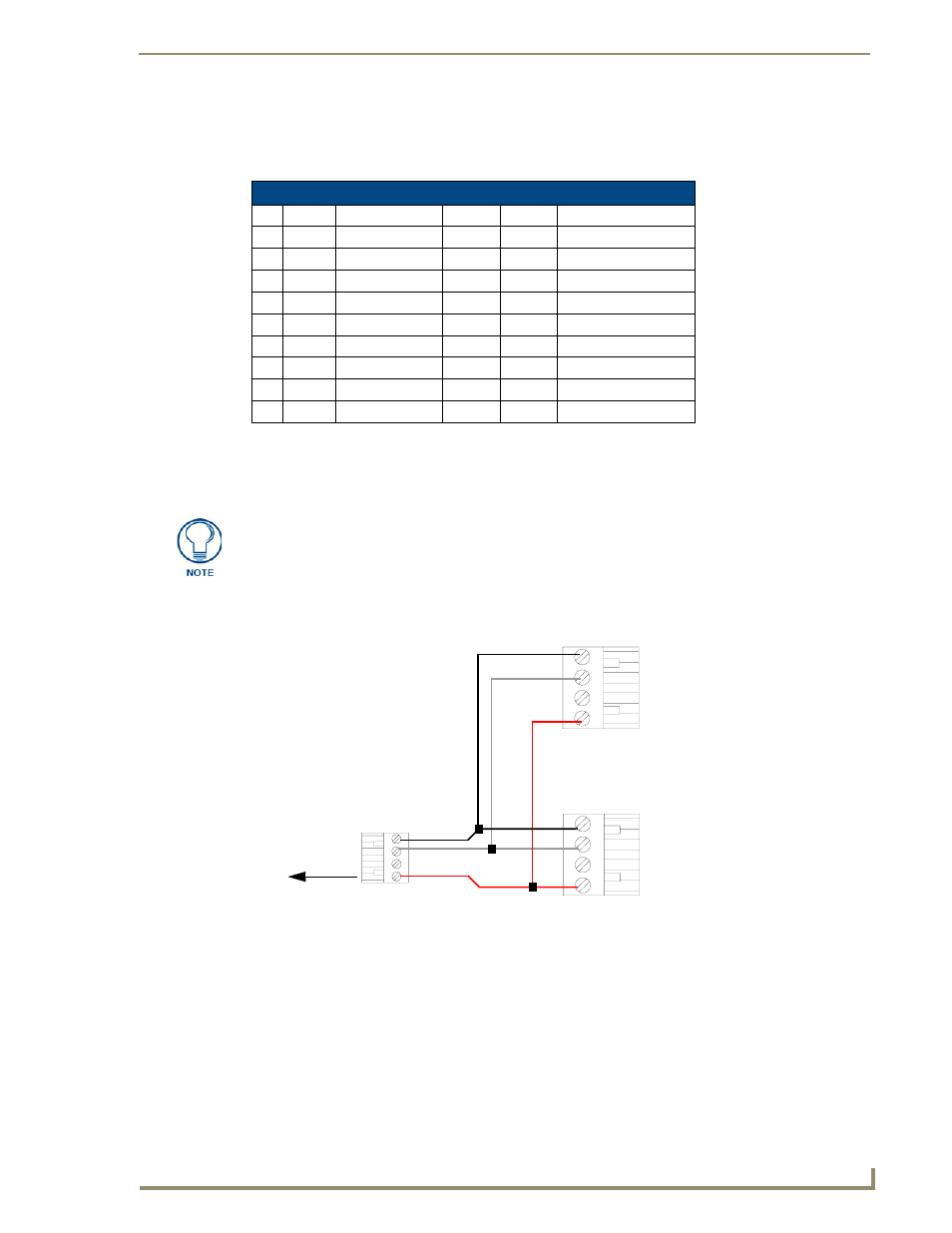
IRX-RX Port: Connection and Wiring
The NI-700 and NI-900 units both have a single rear 4-pin IR receiver port (IR RX).
This port can be used to connect one or more (8 maximum in parallel) optional IRX-SM+ or
IRX-DM+ Decora mount IR receivers to the Integrated Controller as shown in FIG. 6.
RS-232/422/485 Device Port Wiring Specifications
Pin Signal Function
RS-232 RS-422
RS-485
1
RX-
Receive data
X
X (strap to pin 9)
2
RXD
Receive data
X
3
TXD
Transmit data
X
4
TX+
Transmit data
X
X (strap to pin 6)
5
GND
Signal ground
X
X
6
RX+
Receive data
X
X (strap to pin 4)
7
RTS
Request to send
X
8
CTS
Clear to send
X
9
TX-
Transmit data
X
X (strap to pin 1)
The IR RX port functions using AMX IR codes (38 KHz and 455 KHz) and works
ONLY with AMX IR Receivers such as the IRX-DM+ and IRX-SM+.
FIG. 6
IR RX port sample connections (AXlink to NetLinx connectors shown)
PWR
GND
IN
AUX
OUT
AUX OUT
+12 VDC
GND
IRX-SM+ #2
IRX-SM+ #1
To the Integrated
Top view
Top view
Top view
OUT
AUX OUT
+12 VDC
GND
Controller’s rear
IR RX connector