10 splitter module installation, Splitter module installation – ADC ACE-142S/142V User Manual
Page 49
ADCP-96-015 • Issue 1 • July 2004
Page 43
© 2004, ADC Telecommunications, Inc.
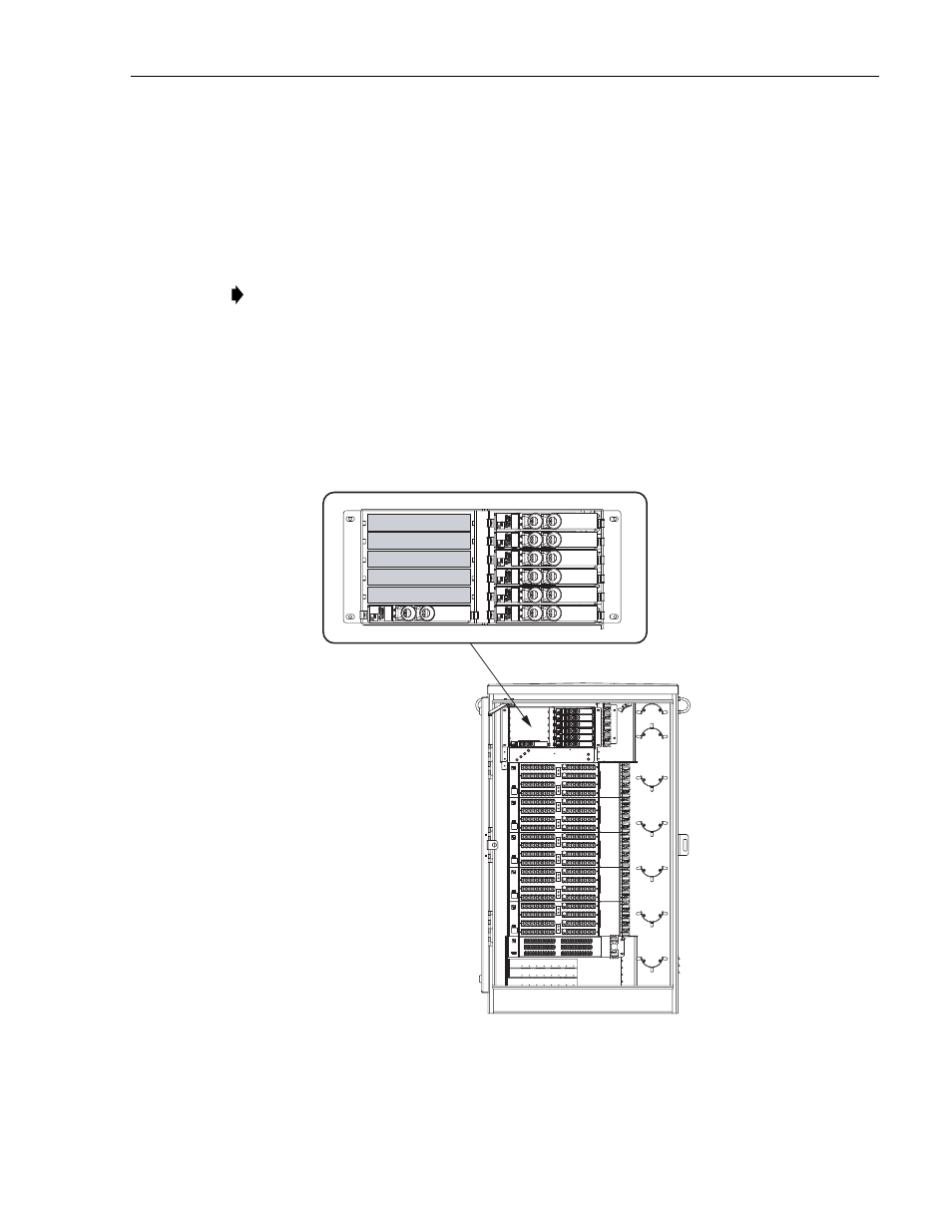
10 SPLITTER MODULE INSTALLATION
The ACE-142S/142V cabinet can accommodate up to twelve 1x8 or 1x32 splitter modules. The
cabinet can support a maximum of 360 output ports for distribution. Use the following
procedure to install additional splitters in the cabinet:
1. Install the splitter module in the next available mounting position as shown in
2. Route the splitter output fibers to the connector storage panel or to the designated
customer port. Refer to
for the routing procedure.
3. Route the splitter input fiber to the designated splice tray at the back of the cabinet as
. Up to 12 fibers may be spliced within each splice tray.
Figure 35. Splitter Module Installation
Note: Install splitters in the order shown in
, beginning on the right side of the
splitter compartment.
19636-A
1
2
3
4
5
6
7
8
9
10
11
12
DETAIL DRAWING OF
SPLITTER MODULES
- 310F (68 pages)
- HiGain H2TU-C-319 List 4E (88 pages)
- H4TU-C-319 List 1 Line Unit (79 pages)
- UTP Switchboard Cable (4 pages)
- FlexWave MMW 125 (4 pages)
- 600F (140 pages)
- Fibre ETSI Solution (8 pages)
- D3LXC-FCA100 (52 pages)
- 420F (106 pages)
- OmniReach OFDT-24 (4 pages)
- P-90-216 (15 pages)
- HiGain T1MF2S04RA (60 pages)
- TrueNet F/UTP Riser Cable (4 pages)
- UltraWAVE GSM Network-In-A-Box 105968AE (4 pages)
- InterReach 850 Cellular (12 pages)
- Soneplex Quad Loop Extender (2 pages)
- Digivance NXD (8 pages)
- Reliable (4 pages)
- GSM Base Station Controller UltraWAVE BSC (4 pages)
- UltraWAVE CDMA Pico BS Plus (2 pages)
- UniPatch GigE Series (4 pages)
- Cross-Connect DSXi (2 pages)
- OmniReach MDU Rapid Fiber System (8 pages)
- Baluns Series (5 pages)
- Universal Radio Head FlexWave (4 pages)
- Double Pair/Line Power G.SHDSL WorldDSL G.S (4 pages)
- FMT Drawers Featuring MicroVAM Modules (4 pages)
- SG-1 (226 pages)
- PWR-AVIS (33 pages)
- H2TU-C-388 (66 pages)
- TrueNet Rack Mount Fiber Enclosures RMG Series (8 pages)
- Universal Transport Platform for Access Networks PONy Express 16 (4 pages)
- TrueNet Augmented Category 6 Patch Cords (2 pages)
- 2 (44 pages)
- HiGain Wideband 3190 WBS-3190 (8 pages)
- TrueNet Termination Block (4 pages)
- Soneplex Broadband System (342 pages)
- LoopStar EtherNID (12 pages)
- Ethernet Distribution Frame TrueNet (2 pages)
- DSX-4R (RZX3) (2 pages)
- 24 AWG STC (4 pages)
- WMX 300 (4 pages)
- MM702G2 (134 pages)
- FlexWave MMX 8000 (4 pages)
- Fiber Optic Panel FL2000 Series (19 pages)