Front panel – Manley VOXBOX - MVBXA 4/2003 User Manual
Page 6
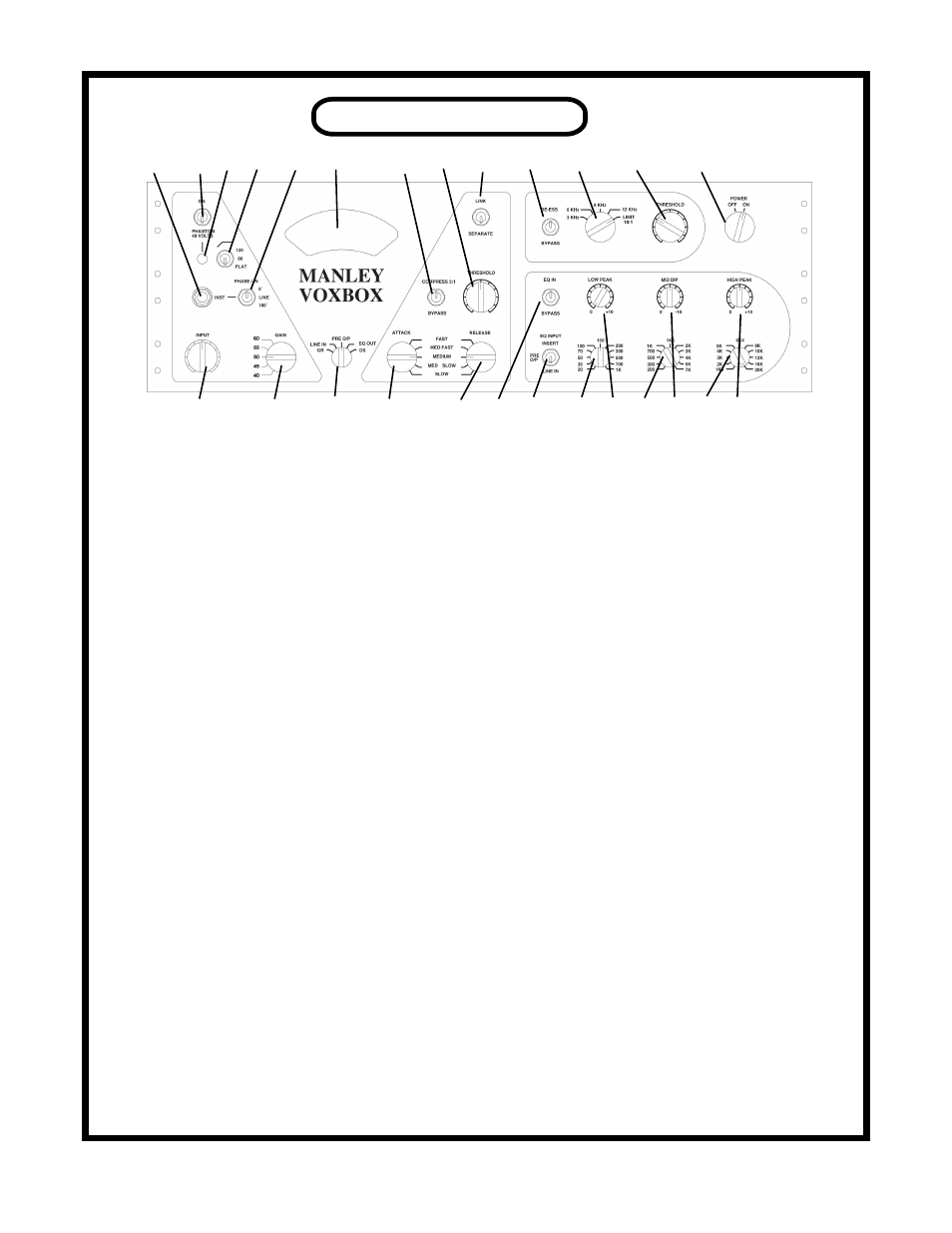
FRONT PANEL
A B C D E H J K N W X Y Z
F G I L M O P Q R S T U V
A. INSTRUMENT INPUT: 100K ohm input impedance. The PHASE switch should be in the middle po-
sition to use this input so that the mic input transformer is disconnected. Inserting a phone jack here will
interupt the back panel LINE INPUT. Compression will lower this impedance and can cause some HF loss
on guitars but a few dB of compression is OK. Two ways around this are use a preamp or effects pedal
between this input and the guitar or use the limiter part of the de-esser.
B. PHANTOM POWER SWITCH: This is a “locking switch” for safety - Pull out to toggle. Turn down
the monitors before toggling. Use the 48 volt phantom power with FET CONDENSOR MICS but not with
dynamic or tube mics. See page 13 for more on phantom power.
C. PHANTOM LED: Lit when phantom power is on.
D. LOW FILTER: This is a minimum phase shift “high pass” filter that is available for the mic, line and
instrument input. The slope is a gentle 6 dB per octave. FLAT = BYPASS
E. PHASE SWITCH: A more correct term is polarity. This function is only available for the mic input. The
“0” position is normal (non-inverting). The “180” position reverses the phase of the mic signal. The mid-
dle position marked “LINE” disconnects the mic transformer and optimizes the LINE and INSTRUMENT
inputs. One might also use that line position to act as a “mute” if no line input is used (or better, the 1/4”
jack is shorted). One uses the 180 position, for example, on the bottom of a snare or with vocalists if the
headphones or mic is out of phase.
F. INPUT: This is the main level control for all inputs to the preamplifier. It is before the compressor and
preamplifier. It allows hot signals to be attenuated before any significant distortion can happen.
G. GAIN SWITCH: This is not a “pad”. It sets the amount of negative feedback which has an effect on
gain, transient accuracy, noise, clipping characteristics, etc. It is normally used as a tone control and/or to
optimise noise. See page 13 for more on this control.
H. VU METER: This is a true standard VU. It is not supposed to “agree” with peak meters. The VU is
preferred for recording to analog tape and is intended to show a reasonable representation of how “loud”
the signal will be heard. Use your tape machine’s meters to safely set an output level.
I. METER SELECT SWITCH: The VU meter shows 3 isolated audio inputs and 2 positions that are used
to indicate the amount of gain reduction from the compressor and de-esser / limiter. Because the VU meter
is a little slow it may not show some fast peak reduction that is actually occurring but will tend to show
the “audibility” of gain changes by the amount and rate of needle swing.
6