Connection module pinout, Led indicators, Important – Axis Communications 231D User Manual
Page 6
Page 6
AXIS 231D+/232D+ Installation Guide
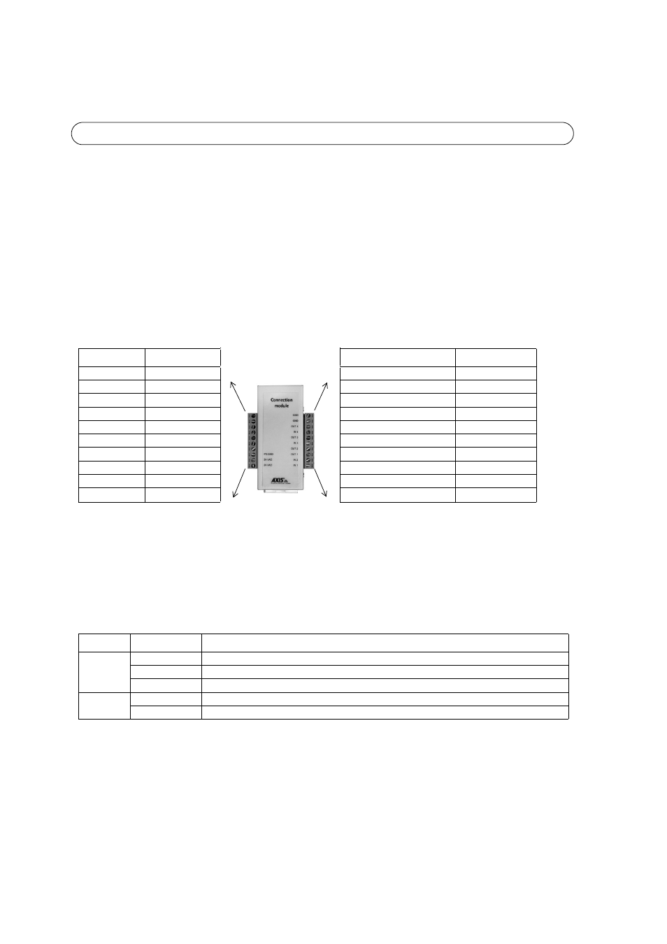
Connection Module Pinout
•
Digital Input (1-4) - connect to GND to activate or leave floating (unconnected) to deactivate
•
Transistor Output (1-4) - Max. load 100mA, max. voltage 24V DC. An open-collector NPN transistor
with the emitter connected to pin 2 (GND). If used with an external relay, a diode must be connected
in parallel with the load for protection against any voltage transients.
LED indicators
Important!
The AXIS 231D+/232D+ is designed for indoor and outdoor use. To use the
camera outdoors, it must be installed in an approved outdoor housing. Please see
www.axis.com for more information on outdoor housings.
Do not use the camera’s dome bubble if it is to be installed in a protective
housing as the use of two dome bubbles will reduce the image quality and cause
image blurring.
Function
Description
Function
Description
n/a
not used
GND
ground
n/a
not used
GND
ground
n/a
not used
Transistor Output 4
See below
n/a
not used
Digital Input 4
See below
n/a
not used
Transistor Output 3
See below
n/a
not used
Digital Input 3
See below
n/a
not used
Transistor Output 2
See below
PS GND
ground
Transistor Output 1
See below
24 VAC
24 VAC
Digital Input 2
See below
24 VAC
24 VAC
Digital Input 1
See below
LED
Color
Description
Network
Green
Steady for connection to 100 Mbit/s network. Flashes for network activity.
Amber
Steady for connection to 10 Mbit/s network. Flashes for network activity.
Unlit
No connection.
Power
Green
Normal operation.
Amber
Flashes green/amber during firmware upgrade.
!