Asus NCLV-D User Manual
Page 33
A S U S N C L V - D S e r i e s
A S U S N C L V - D S e r i e s
A S U S N C L V - D S e r i e s
A S U S N C L V - D S e r i e s
A S U S N C L V - D S e r i e s
2 - 1 3
2 - 1 3
2 - 1 3
2 - 1 3
2 - 1 3
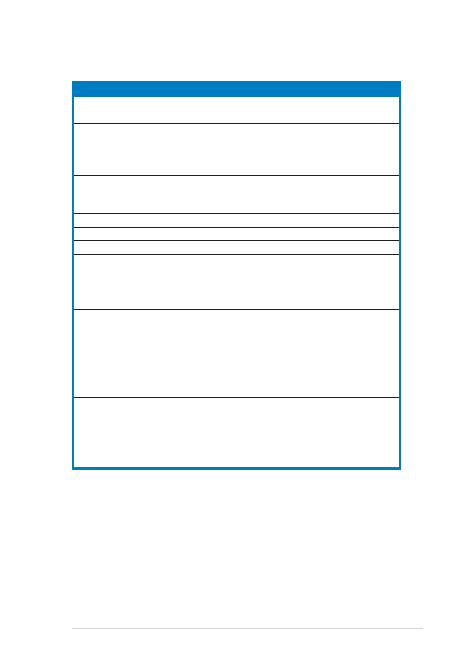
I n t e r n a l c o n n e c t o r s
I n t e r n a l c o n n e c t o r s
I n t e r n a l c o n n e c t o r s
I n t e r n a l c o n n e c t o r s
I n t e r n a l c o n n e c t o r s
P a g e
P a g e
P a g e
P a g e
P a g e
1.
Floppy disk drive connector (34-1 pin FLOPPY)
2-30
2.
IDE connectors (40-1 pin PRI_IDE1, SEC_IDE1)
2-30
3.
Serial ATA connectors (7-pin SATA1, SATA2)
2-31
4.
Serial ATA RAID connectors (7-pin SATA_RAID1, SATA_RAID2,
SATA_RAID3, SATA_RAID4)
(Optional)
2-32
5.
SCSI connector (68-pin SCSI1)
2-33
6.
Hard disk activity LED connector (2-pin HDLED1)
2-34
7.
CPU, Chassis, and Power Fan connectors (3-pin CPU_FAN1/2,
REAR_FAN1/2, FRNT_FAN1/2)
2-34
8.
USB connectors (10-1 pin USB56, USB78)
2-35
9.
Serial port connector (10-1 pin COM2)
2-35
10. SSI power connectors (24-pin EATXPWR1, 8-pin ATX12V1)
2-36
11. Backplane SMBus connector (6-1 pin BPSMB1)
2-37
12. Power Supply SMBus connector (6-1 pin PSUSMB1)
2-37
13. Parallel port connector (26-1 pin LPT1)
2-38
14. BMC Connector (16-pin BMCCONN1)
2-38
15. Auxiliary panel connector (20-pin AUX_PANEL1)
2-39
Chassis intrusion connector (3-pin CASEOPEN)
2-39
LAN1 Link activity LED (2-pin LAN1_LINKACTLED)
2-39
LAN2 Link activity LED (2-pin LAN2_LINKACTLED)
2-39
Locator LED 1 (2-pin LOCATORLED1)
2-39
Locator LED 2 (2-pin LOCATORLED2)
2-39
Locator Button/Switch (2-pin LOCATORBTN)
2-39
Front Panel System Bus (6-1 pin)
2-39
16. System panel connector (20-pin PANEL1)
2-40
System power LED (Green 3-pin PLED)
2-40
Hard disk drive activity LED (Red 2-pin IDE_LED)
2-40
System warning speaker (Orange 4-pin SPEAKER)
2-40
ATX power button/soft-off button (Yellow 2-pin PWRSW)
2-40
Reset button (Blue 2-pin RESET)
2-40