Asus P5GPL-X User Manual
Page 42
1 - 3 0
1 - 3 0
1 - 3 0
1 - 3 0
1 - 3 0
C h a p t e r 1 : P r o d u c t i n t r o d u c t i o n
C h a p t e r 1 : P r o d u c t i n t r o d u c t i o n
C h a p t e r 1 : P r o d u c t i n t r o d u c t i o n
C h a p t e r 1 : P r o d u c t i n t r o d u c t i o n
C h a p t e r 1 : P r o d u c t i n t r o d u c t i o n
5 .
5 .
5 .
5 .
5 .
C h a s s i s i n t r u s i o n c o n n e c t o r ( 4 - 1 p i n C H A S S I S )
C h a s s i s i n t r u s i o n c o n n e c t o r ( 4 - 1 p i n C H A S S I S )
C h a s s i s i n t r u s i o n c o n n e c t o r ( 4 - 1 p i n C H A S S I S )
C h a s s i s i n t r u s i o n c o n n e c t o r ( 4 - 1 p i n C H A S S I S )
C h a s s i s i n t r u s i o n c o n n e c t o r ( 4 - 1 p i n C H A S S I S )
This connector is for a chassis-mounted intrusion detection sensor or
switch. Connect one end of the chassis intrusion sensor or switch
cable to this connector. The chassis intrusion sensor or switch sends a
high-level signal to this connector when a chassis component is
removed or replaced. The signal is then generated as a chassis
intrusion event.
By default, the pins labeled “Chassis Signal” and “Ground” are shorted
with a jumper cap. Remove the jumper caps only when you intend to
use the chassis intrusion detection feature.
P5GPL-X
®
P5GPL-X Chassis intrusion connector
CHASSIS
+5VSB_MB
Chassis Signal
GND
(Default)
Never connect a 1 3 9 4 c a b l e
1 3 9 4 c a b l e
1 3 9 4 c a b l e
1 3 9 4 c a b l e
1 3 9 4 c a b l e to the USB connectors. Doing so will
damage the motherboard!
6 .
6 .
6 .
6 .
6 .
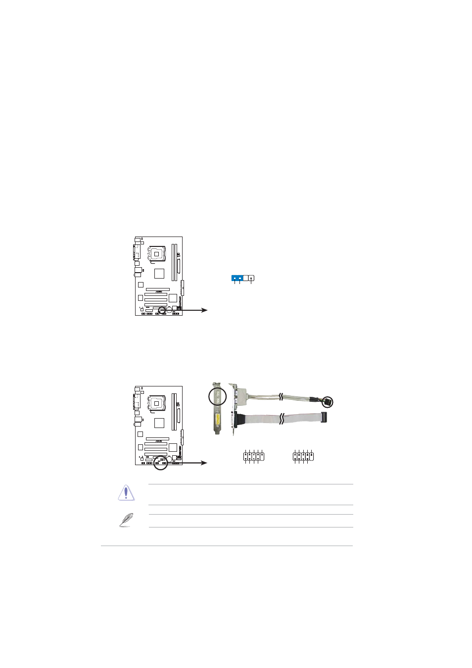
U S B c o n n e c t o r s ( 1 0 - 1 p i n U S B 5 6 , U S B 7 8 )
U S B c o n n e c t o r s ( 1 0 - 1 p i n U S B 5 6 , U S B 7 8 )
U S B c o n n e c t o r s ( 1 0 - 1 p i n U S B 5 6 , U S B 7 8 )
U S B c o n n e c t o r s ( 1 0 - 1 p i n U S B 5 6 , U S B 7 8 )
U S B c o n n e c t o r s ( 1 0 - 1 p i n U S B 5 6 , U S B 7 8 )
These connectors are for USB 2.0 ports. Connect the USB/GAME
module cable to any of these connectors, then install the module to a
slot opening at the back of the system chassis.
P5GPL-X
®
P5GPL-X USB 2.0 connectors
USB56
USB+5V
USB_P6-
USB_P6+
GND
NC
USB+5V
USB_P5-
USB_P5+
GND
1
USB78
USB+5V
USB_P8-
USB_P8+
GND
NC
USB+5V
USB_P7-
USB_P7+
GND
1
Game/MIDI module is purchased separately.