Iii. hardware setup – Asus P5-99VM User Manual
Page 27
ASUS P5-99VM User’s Manual
27
III. HARDWARE SETUP
Connectors
III. H/W SETUP
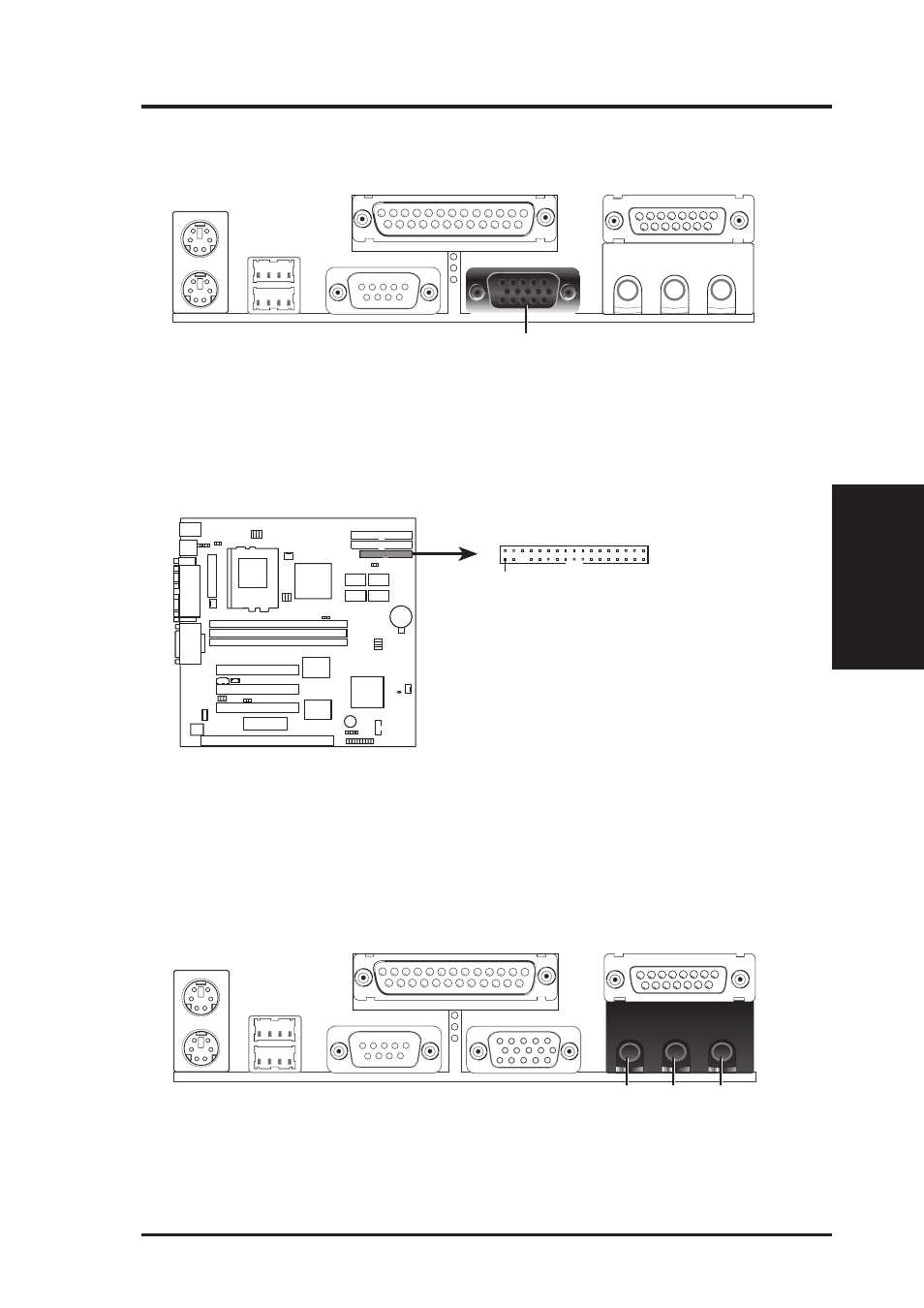
6. Monitor (VGA) Output Connector (15-pin Female)
This connector is for output to a VGA-compatible device.
VGA Monitor (15-pin Female)
7. Floppy drive connector (FLOPPY, 34-1 pin block )
This connector supports the provided floppy drive ribbon cable. After connect-
ing the single end to the board, connect the two plugs on the other end to the
floppy drives. (Pin 5 is removed to prevent inserting in the wrong orienta-
tion when using ribbon cables with pin 5 plugged).
PIN 1
P5-99VM Floppy Disk Drive Connector
NOTE: Orient the red markings on
the floppy ribbon cable to
PIN 1
0
1
8. Audio Port Connectors (Three 1/8” Female) (with optional onboard audio)
Line Out can be connected to headphones or preferably powered speakers.
Line In allows tape players or other audio sources to be recorded by your com-
puter or played through the Line Out. Mic allows microphones to be connected
for inputing voice.
Mic
Line In
Line Out
1/8" Stereo Audio Connectors
- P5B Premium Vista Edition (188 pages)
- P5B (140 pages)
- P5B (56 pages)
- P5KPL-VM/1394/SI (94 pages)
- M2N68-CM (28 pages)
- P5AD2-E Premium (2 pages)
- P5GD1-VM (88 pages)
- P5AD2 Premium (8 pages)
- P5GD1-VM (92 pages)
- DELUXE A7N8X-E (114 pages)
- P5KPL-AM SE (62 pages)
- P5KPL-AM SE (40 pages)
- P5KPL-AM SE (38 pages)
- P4S8X-X (64 pages)
- P5K-VM (98 pages)
- K8V-X SE (82 pages)
- M2N68-AM SE2 (40 pages)
- P4P800 SE (125 pages)
- P4P800 SE (16 pages)
- DELUXE SERIES M3A32-MVP (176 pages)
- P5AD2 Deluxe (148 pages)
- M4A79 Deluxe (122 pages)
- A7V266-E (108 pages)
- Application Manual (8 pages)
- Application Manual (2 pages)
- Application Manual (6 pages)
- Application Manual (9 pages)
- Application Manual (3 pages)
- Application Manual (1 page)
- Application Manual (5 pages)
- Application Manual (11 pages)
- Application Manual (10 pages)
- Application Manual (4 pages)
- M4A88T-I DELUXE (70 pages)
- M4A88T-I DELUXE (44 pages)
- P9X79 DELUXE (2 pages)
- RAMPAGE IV GENE (1 page)
- P9X79 (156 pages)
- P8H61-M PLUS V3 (64 pages)
- A85XM-A (78 pages)
- M4A78L-M LE (64 pages)
- M2N68-AM (96 pages)
- M2N68-AM (62 pages)
- M2N68-AM (38 pages)
- Blitz Formula (1 page)