Mini-sas y-cable options – HP ProLiant DL388e Gen8 Server User Manual
Page 46
Hardware options installation 46
8.
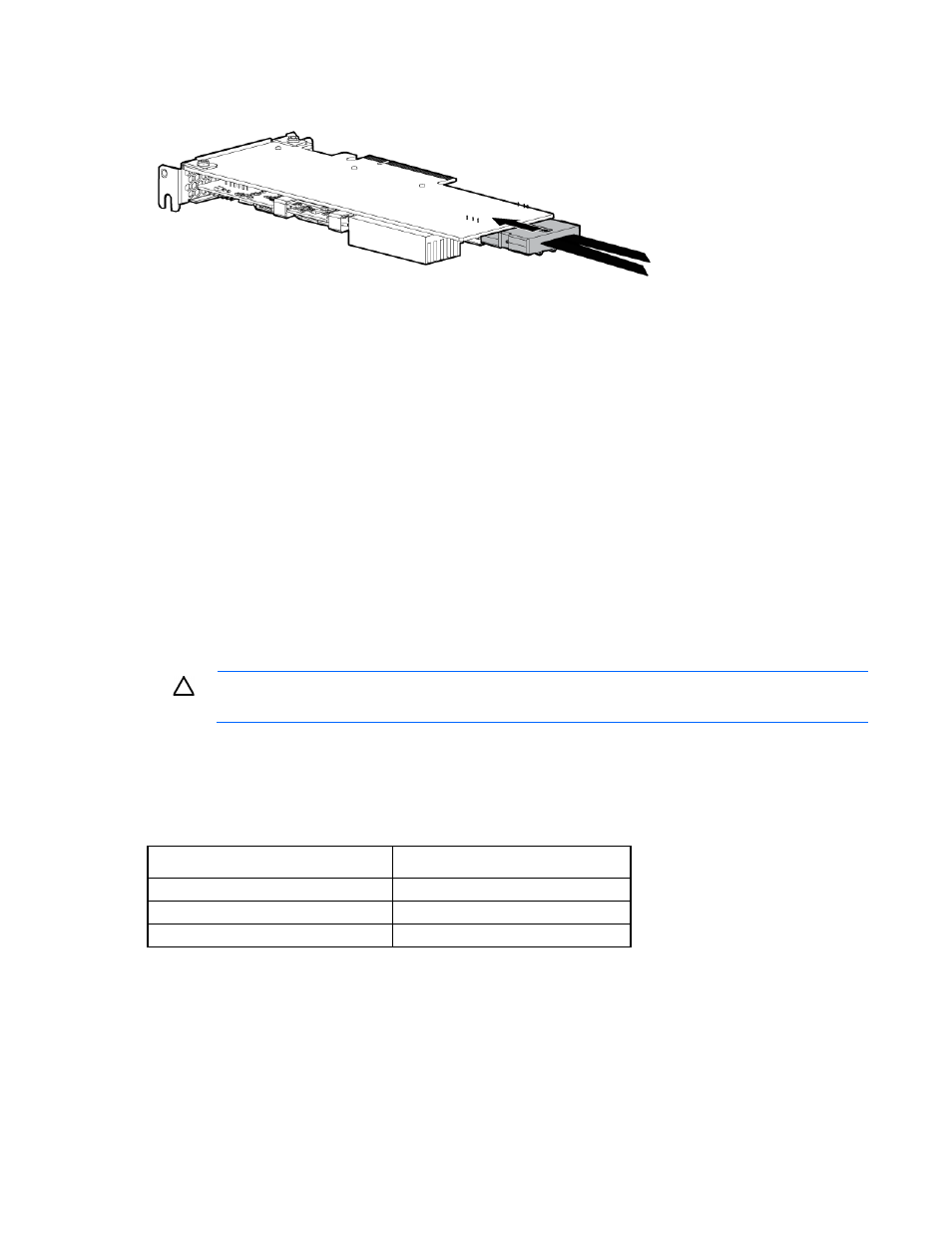
Connect the common end of the Mini-SAS Y-cable to the controller option.
9.
Install the PCI riser cage ("
" on page
10.
Route the split ends of the Mini-SAS Y-cable along the side of the system board towards the front chassis,
and then connect the cable to the drive backplane.
The Mini-SAS cable routing from the secondary PCI riser cage is only supported in the 8+8 SFF drive
configuration.
11.
Connect the rest of the drive cables required in this drive configuration. For more information, see
"Storage cabling (on page
)."
12.
Install the PCI riser cage ("
" on page
13.
If you intend to use an FBWC module and capacitor pack, install these options now ("
FBWC module and capacitor pack
" on page
14.
Install the air baffle (on page
15.
Install the access panel (on page
16.
Install the server into the rack ("
Installing the server into the rack
" on page
17.
CAUTION:
To prevent improper cooling and thermal damage, do not operate the server unless
all bays are populated with either a component or a blank.
18.
Install the drives ("
" on page
Mini-SAS Y-cable options
The Mini-SAS Y-cables in these option kits support the following drive configurations.
Drive configuration
Mini-SAS Y-cable required
8 LFF
690 mm
8 SFF
540 mm
8+8 SFF*
540 mm and 780 mm
*
This drive configuration requires the installation of two HP Smart Array P430 controller boards in the full-height side of
the primary PCI riser cage.
To connect the cable option:
1.
Power down the server (on page
2.
Remove all power:
a.
Disconnect each power cord from the power source.