Component identification, Port side of the switch, Internal ports summary – HP Cisco MDS 8Gb Fabric Switch for HP BladeSystem c-Class User Manual
Page 8: Switch redundancy
8
1 Overview
Component identification
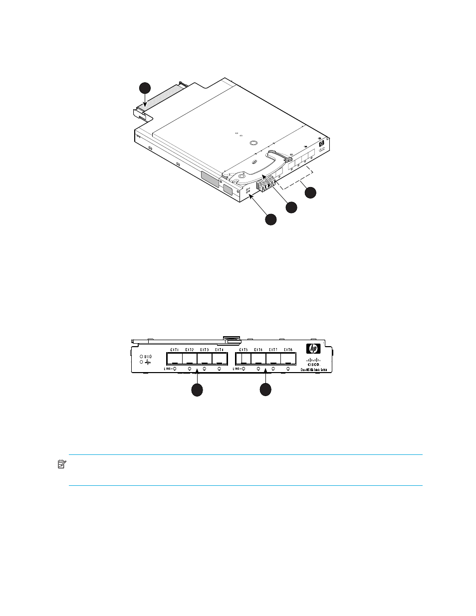
identifies the physical components of the Cisco MDS 8Gb Fabric Switch.
Figure 1
Identifying components
Port side of the switch
identifies Cisco MDS 8Gb Fabric Switch external ports (ports EXT 1 through EXT 4 and ports EXT
5 through EXT 8).
Figure 2
Cisco MDS 8Gb Fabric Switch external ports
NOTE:
See
Interpreting LED activity
for complete information on Cisco MDS 8Gb Fabric Switch LEDs.
Internal ports summary
Sixteen logical internal ports (numbered 1 through 16) connect sequentially to server bays 1 through 16
with the enclosure midplane. Server bay 1 is connected to Switch Port 1, Server bay 2 is connected to
Switch port 2, and so forth.
Switch redundancy
The HP BladeSystem c-Class is engineered as a no-single-point-of-failure bladed solution. Attributes that
contribute to switch redundancy include:
1
Midplane connector
2
External SFP ports (Two
populated, six unpopulated
3
Installation handle
4
UID and Health LEDs)
scale: 3/8" = 1"
17
18
19
20
!
Cisco MDS 8Gb F
abr
ic Switch
EXT 8
EXT 7
EXT 6
EXT5
2
3
4
196990
1
1
Left bank—EXT 1, EXT 2, EXT 3
and EXT 4
2
Right bank—EXT 5, EXT 6, EXT 7
and EXT 8
1
2
196996