Trunking groups, ports and masters, Figure 1-2, Trunking groups – HP StorageWorks 8B FC Entry Switch User Manual
Page 11: Trunking ports
ISL Trunking User’s Guide
1-3
Introducing ISL Trunking
1
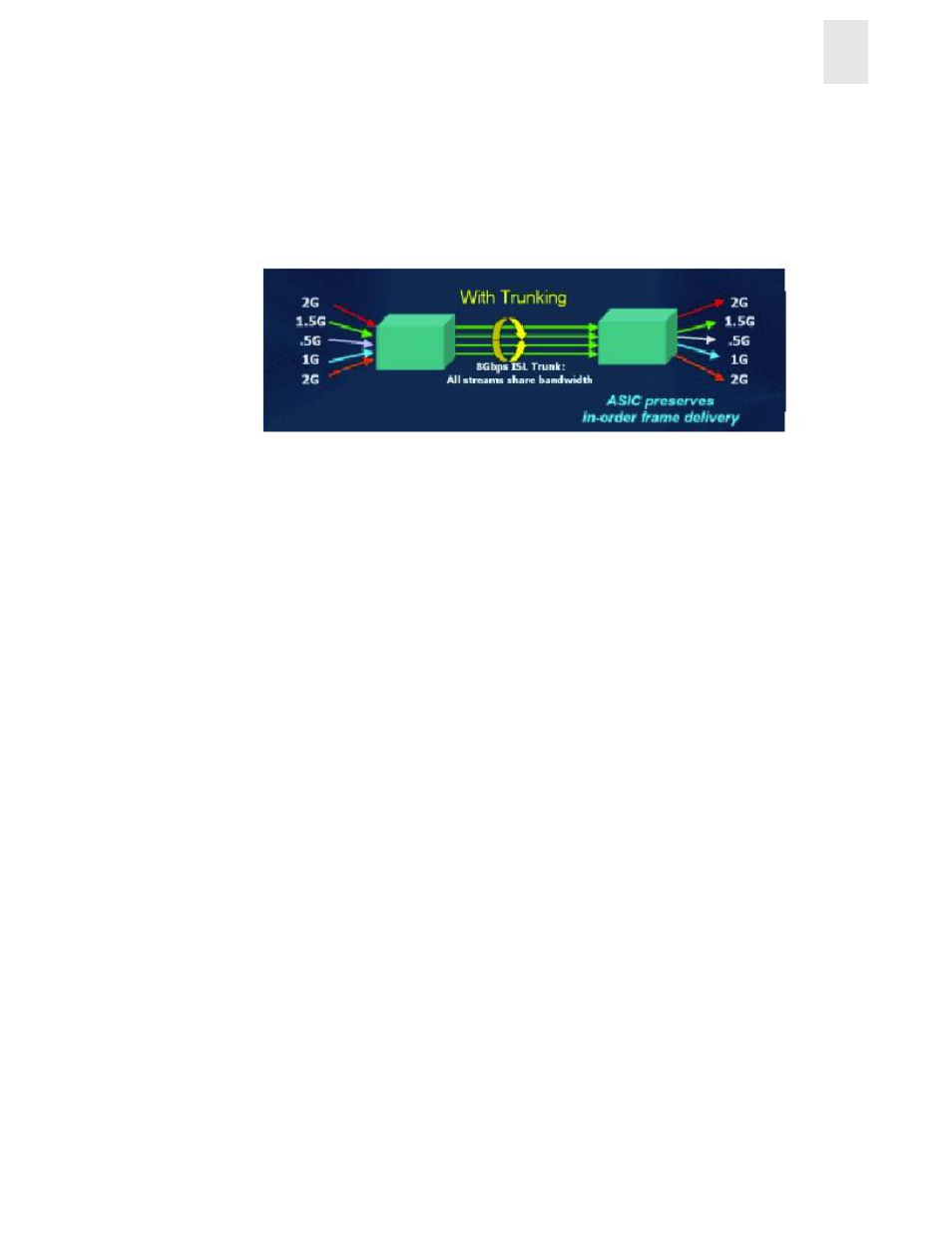
In
, four ISLs provide 8Gb/Sec of total throughput. With the implementation of ISL
Trunking, bandwidth is shared across the trunked ISLs, permitting a total throughput of 2Gb/Sec. +
1.5Gb/Sec + 0.5Gb/Sec + 1 Gb/Sec + 2Gb/Sec, or 7Gb/Sec. Because the trunk aggregates the four
individual paths into one and preserves in-order deliver of frames, the total throughput is increased
compared to a non-trunked group of ISLs.
Figure 1-2
Routing with the ISL Trunking Feature
Trunking Groups, Ports and Masters
ISL Trunking dynamically performs load sharing, at the frame level, across a set of available links
between two adjacent switches to establish a trunking group. Ports that belong to a trunking group
are called trunking ports. One port is used to assign traffic for the group, and is referred to as the
trunking master.
Trunking Groups
A trunking group is identified by the trunking master that represents the entire group. The rest of
the group members are referred to as slave links that help the trunking master direct traffic across
ISLs, allowing efficient and balanced in-order communication.
Trunking Ports
Trunking ports in a trunking group must meet the following criteria:
•
Port must be configured as E_ports.
•
Ports must reside in the same contiguous four-port groups. For example: 0-3, 4-7, 8-11, 12-15.
•
Ports must be set to run at the 2G speed.
•
The cable difference between all ports in a trunking group must be less than 400 meters, and
should be kept to 30 meters or less within a trunk to ensure optimal performance and
bandwidth utilization.
Note:
Short Wave Length (SWL) and Long Wave Length (LWL) fiber optics can be intermixed
within a trunking group.