Figure 2-2, View of inner component rail – HP Integrity NonStop J-Series User Manual
Page 15
Installing and Configuring the Tape Drive for the
NonStop NS-Series Integrity Server
5344-2SE Tape Drive Installation and User’s Guide — 546010-001
2 -3
Installation
c.
Insert the pins in the front mounting plate of the outer rack rails into the
previously marked holes in the front vertical mounting bars of the rack. The
rack rails will lock securely into place.
d. Extend the rack rails past the rear vertical mounting bar and insert the pins in
the mounting bracket into the previously marked holes in the rack. The rack
rails will lock securely into place when the end of the rails are pushed forward.
e. Remove the pins and threaded plates from both ends of each outer rack rail.
These pieces will not be used.
f.
Attach the front mounting plate of each outer rail to the rack using four 10-32
screws in the previously marked holes in the front vertical mounting bars of the
rack.
g. Extend the rack rails past the rear vertical mounting bars and attach the back
mounting plate of each outer rail to the rack using four 10-32 screws in the
previously marked holes.
h. Extend the stabilizing feet if provided on your rack.
i.
Extend the left and right rack rails from the front of the rack.
j.
Align the rear of the component rails on the tape enclosure with the front ends
of the rack rails, then slide the unit fully into the rack.
k.
Attach the unit to the rack using the two thumbscrews, there is one on each
side. You can also tighten these screws with a phillips head screwdriver.
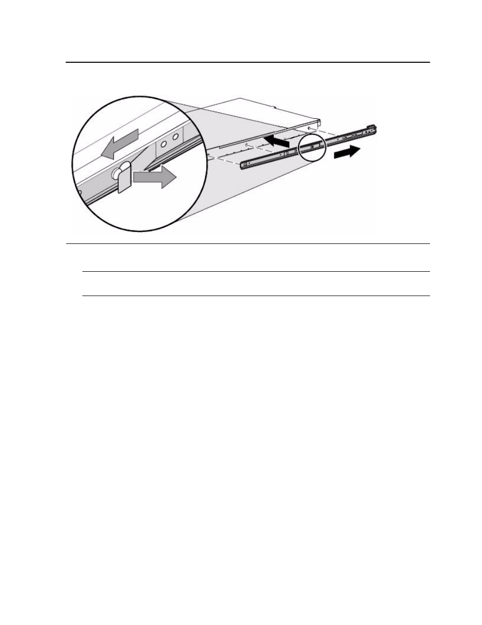
Figure 2-2. View of Inner Component Rail
Note. To remove the component rail, pull out the spring-loaded tab on the side of the rail
and slide it forward.