Cont. ), Wiring connections – Axis Communications 25734 User Manual
Page 8
- -
Wiring Connections
CONTROL
RJ45 Ethernet Connector
ALARMS
1
Alarm 1
Blue
2
Alarm 2
Violet
3
Alarm 3
Gray
4
Common
White
POWER
1
Camera Power (24VAC)
Red
2
Camera Power (24VAC)
Orange
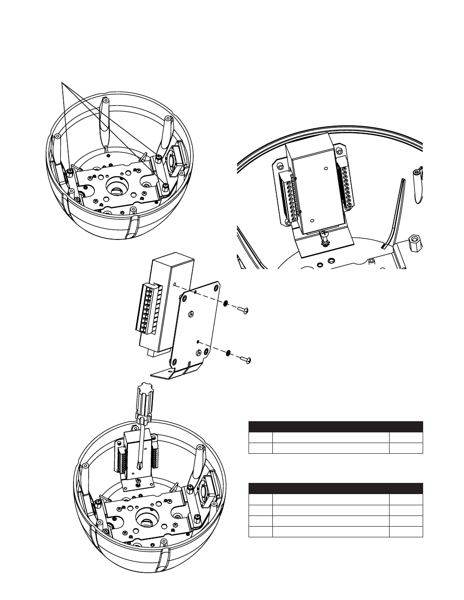
Installing Axis 231D/232D Camera
(cont.)
7. Then start (3) 8-32x3/8” phillips head screws onto the (3) ½" spacers inside
the housing. Be sure to place the screws so that they line up with the (3)
open slots on the quick release bracket, the screws on the bottom of the
camera, see diagram below.
(3) 8-32 x 3/8"screws
8. Locate the connector block,
which is included with the
camera. Then located the
connector block bracket,
which is included with the
housing. Attach the block
to the bracket as shown
in the following diagram.
Use the M3 screws
and washers that are
located in the housing
packet.
9. Attach the connector
block assembly to the
housing using (1) 6-
32x3/8” screw and star
washer located in the
housing packet.
10. Make wiring connections to connector block assembly per
camera instructions.
- Camera Station (47 pages)
- Fixed Dome Network Camera AXIS P3301 (74 pages)
- AXIS 214 PTZ (70 pages)
- AXIS MFD-R (75 pages)
- AXIS 213 PTZ (2 pages)
- 232D (55 pages)
- 232D (2 pages)
- AXIS 223 (1 page)
- Fixed Dome Network Camera AXIS P3301-V (50 pages)
- 2100 (2 pages)
- 210 (66 pages)
- AXIS T8311 (34 pages)
- AXIS 206W (34 pages)
- 209FD/FD-R (71 pages)
- AXIS 206M (36 pages)
- 213 PTZ (3 pages)
- 216FD/FD-V (64 pages)
- HPV42K1A000 (2 pages)
- AXIS T95A00 (73 pages)
- AXIS 209MFD-R (73 pages)
- AXIS T8310 (10 pages)
- AXIS 209FD-R (73 pages)
- 2120 (2 pages)
- 2120 (68 pages)
- AVTPSC (2 pages)
- AXIS Q1755 (59 pages)
- Axis 216MFD (74 pages)
- AXIS FD-R M12 (46 pages)
- AXIS 209MFD (73 pages)
- 207W (59 pages)
- 230 MPEG-2 (62 pages)
- 2130 (2 pages)
- Axis 211A (76 pages)
- Axis 210 (83 pages)
- AXIS 233D (69 pages)
- AXIS 221 (64 pages)
- 211 (66 pages)
- 207 (54 pages)
- Axis 216FD-V (4 pages)
- IP-Surveillance (8 pages)
- AXIS 207 (73 pages)
- AXIS 223M (70 pages)
- 2401 (87 pages)
- AXIS 211M (2 pages)
- 207MW (60 pages)