9 sysclk and sysclk# dc characteristics, Table 15, Sysclk and sysclk# dc characteristics – AMD Athlon 27493 User Manual
Page 47
Chapter 8
Electrical Data
35
26237C—May 2003
AMD Athlon™ XP Processor Model 10 Data Sheet
Preliminary Information
8.9
SYSCLK and SYSCLK# DC Characteristics
Table 15 shows the DC characteristics of the SYSCLK and
SYSCLK# differential clocks. The SYSCLK signal represents
CLKIN and RSTCLK tied together while the SYSCLK# signal
represents CLKIN# and RSTCLK# tied together. For more
information about SYSCLK and SYSCLK#, see “SYSCLK and
S Y S C L K # ” o n p a g e 7 7 a n d Ta b l e 2 3 , “ P i n N a m e
Abbreviations,” on page 56.
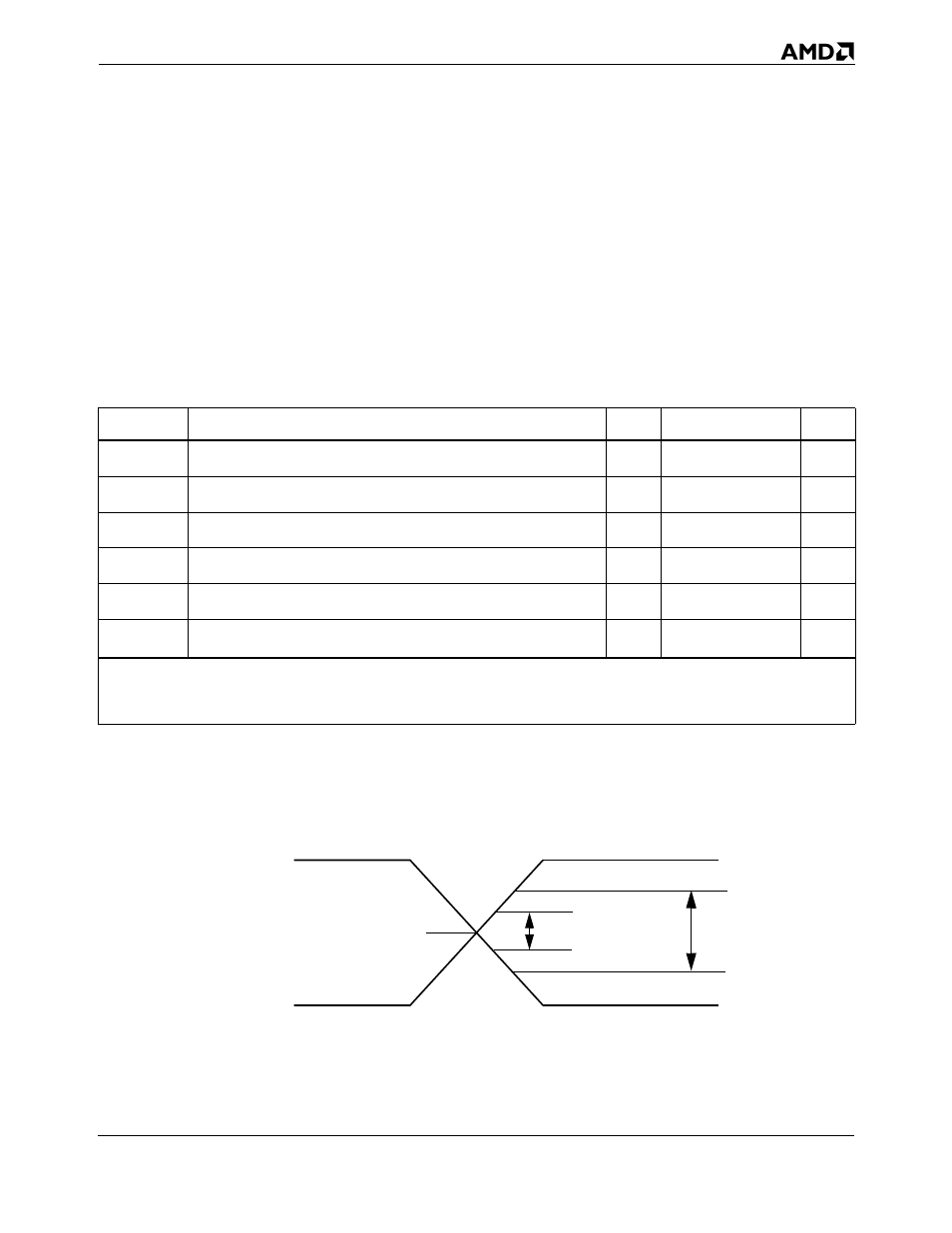
Figure 11 shows the DC characteristics of the SYSCLK and
SYSCLK# signals.
Figure 11. SYSCLK and SYSCLK# Differential Clock Signals
Table 15. SYSCLK and SYSCLK# DC Characteristics
Symbol
Description
Min
Max
Units
V
Threshold-DC
Crossing before transition is detected (DC)
400
mV
V
Threshold-AC
Crossing before transition is detected (AC)
450
mV
I
LEAK_P
Leakage current through P-channel pullup to V
CC_CORE
–1
mA
I
LEAK_N
Leakage current through N-channel pulldown to VSS (Ground)
1
mA
V
CROSS
Differential signal crossover
V
CC_CORE
/ 2±100
mV
C
PIN
Capacitance *
4
25 *
pF
Note:
*
The following processor inputs have twice the listed capacitance because they connect to two input pads—SYSCLK and SYSCLK#.
SYSCLK connects to CLKIN/RSTCLK. SYSCLK# connects to CLKIN#/RSTCLK#.
V
CROSS
V
Threshold-DC
= 400mV
V
Threshold-AC
= 450mV