Asus P7P55D-E LX User Manual
Page 35
ASUS P7P55D-E LX
1-23
3.
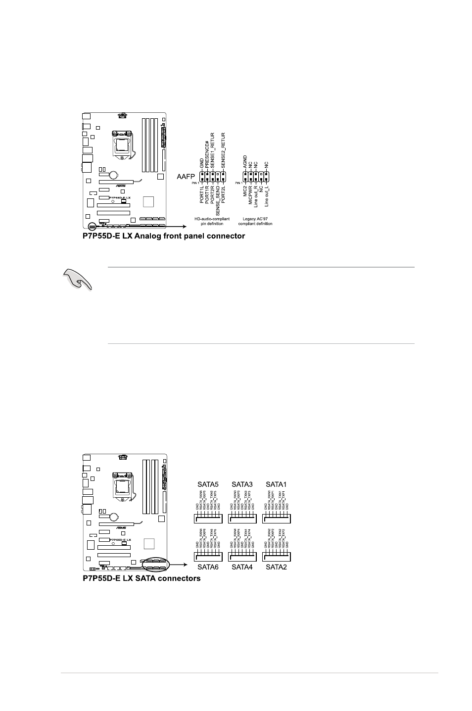
Front panel audio connector (10-1 pin AAFP)
This connector is for a chassis-mounted front panel audio I/O module that supports
either HD Audio or legacy AC`97 audio standard. Connect one end of the front panel
audio I/O module cable to this connector.
• We recommend that you connect a high-definition front panel audio module to this
connector to avail of the motherboard’s high-definition audio capability.
• If you want to connect a high-definition front panel audio module to this connector, set
the
Front Panel Type item in the BIOS setup to [HD Audio]. If you want to connect an
AC'97 front panel audio module to this connector, set the item to
[AC97]. By default, this
connector is set to
[HD Audio].
4.
Serial ATA connectors (7-pin SATA1-6)
These connectors are for the Serial ATA signal cables for Serial ATA hard disk drives
and optical disc drives.
If you installed Serial ATA hard disk drives, you can create a RAID 0, 1, 5, and 10
configuration with the Intel
®
Matrix Storage Technology through the onboard Intel
®
P55
chipset.