Metal – Water Inc WI-BG-PURE User Manual
Page 12
6
METAL
PRODUCT WATER FAUCET INSTALLATION AND SYSTEM CONNECTIONS
Install faucet on flat surface at least 2" in diameter. Unused 1-1/4" hole is ideal.
Steps unique to a specific configuration are so noted. All other steps are common to either configuration.
New Faucet Installation
Refer to Faucet Site Preparation, Page 5.
Replacement Faucet Installation
Verify size of existing hole is 1 1/4".
NOTE: Item callouts refer to Page 7, Figure 7 unless
noted otherwise.
1. Air Gap Only: Verify faucet body, metal base
washer, and rubber base washer are in place above
sink (Items 1, 3, and 2).
Non-Air Gap Only: Verify faucet body, metal base
washer, and rubber base washer are in place above
sink (Items 1, 3, and 2).
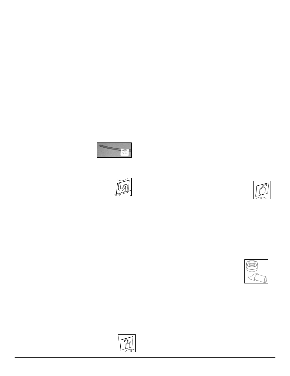
2. CAUTION: Flow Restrictor (FLR) is installed inside
the 1/4” red tubing on the end with the label. DO NOT
TRIM THE END OF THE 1/4" FLR
RED TUBING THAT INCLUDES
THE LABEL (See Figure 8.A/B).
Air Gap Only: Install 3/8” red tubing from
Installation Kit onto larger hose barb as shown in
Figure 7.
3. Air Gap Only: Connect the 1/4” FLR red
tubing end with FLR label between the
module red collet near symbol shown
and the faucet:
a. Air Gap Only: Insert the 3/8” red tube into the
mounting hole.
b. Air Gap Only: Insert the 1/4" FLR red tubing
upwards through mounting hole.
c. Air Gap Only: Position module in desired
location. Trim the end of FLR tubing without label
to desired length. Attach FLR tubing onto smaller
hose barb as shown in Figure 7.
4. Lower faucet into mounting hole and place
faucet over hole.
5. Air Gap Only: Install slotted washer, spacer, faucet
washer, and nut onto faucet nipple below sink and
snug them up (Items 4, 5, 6, and 7). Be sure to
properly align faucet before tightening. Do not over
tighten.
Non-Air Gap Only: Install locating washer, faucet
washer and nut (Items 4A, 6, and 7) onto faucet
nipple below sink and snug them up. Be sure to align
faucet properly before tightening. Do not over tighten.
6. Install faucet connector (Item 8), packaged with
faucet, onto faucet nipple. Install 3/8” blue tube into
faucet connector.
7. Trim 3/8” blue tube to desired length. Install
3/8” blue tube into 3/8” blue collet located on
side of module near symbol as shown.
8. CAUTION: Red 3/8" tube connecting product water
faucet to drain saddle must run vertically (or as
closely as possible) with no sharp bends or loops
(See Page 4, Figure 4).
Connect loose ends of tubing as follows:
a. Non-Air Gap Only: Connect 1/4" FLR red tubing
to 1/4" drain saddle using compression nut.
b. Air Gap Only: Connect 3/8” red tubing to
3/8" on drain saddle using compression nut.
Refer to steps 2-4 in Polymer Tank Assembly for use
of compression nuts.
Storage Tank Connection - Metal Tank Assembly
NOTE: The following instructions refer to Page IV,
Figure 1.B, Items 2 & 3.
NOTE: Refer to Page 2, Inter-Component Connections
for instructions on how to install tubing.
1. Install ball valve (located inside of master pack box)
onto the 1/4” storage tank nipple. Use thread sealing
tape to seal threads between ball valve and nipple.
2. Connect 3/8” white tubing between module
(near symbol as shown) and storage tank
shut-off valve.
3. The basic installation is complete and
system is ready for activation (see Page 9).
NOTE: With the storage tank empty, ensure the air-cell
pre-charge is set to manufacturer’s instructions marked
on
tank. Use a hand power air pump to increase, if
necessary.
WARNING: Never use an air compressor to fill air cell of
a reverse osmosis system storage tank. Damage to the
tank and/or air cell can occur.
NOTE: Optional stem elbows have been
supplied to allow installations with limited
space. Connect the stem elbow into the
inlet, faucet, tank and drain parts as
required before connecting tubing.