Atmel ATAK2270 User Manual
Page 28
Host Software
RFID Application Kit ATAK2270 User Manual
5-15
4871E–RFID–04/08
5.3.5
ATA5570 Multifunction Read/Write Transponder with Sensor Input
The ATA5570 is derived from the T5557; however, it is enhanced by an additional sensor input. Depend-
ing on the connected sensor resistance, the uplink data is sent either in direct or inverse mode.
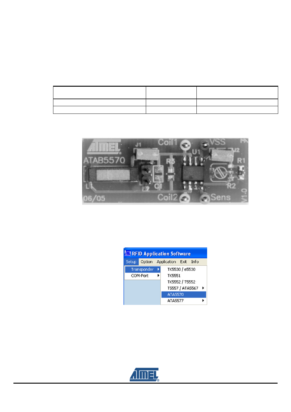
To promote the sensor functionality, a special application board is available, ATAB5570.
Figure 5-18. RFID Development Board ATAB5570
Even though the ATA5570 transponder has its own menu item (see
), the software routines
of the T5557 are used. Hence, to operate the ATA5570 refer to the instructions for the T5557/ATA5567,
see
Section 5.3.4 ”T5557/ATA5567 Multifunction Read/Write Transponder”
.
Figure 5-19. ATA5570 Mode Selection
Note:
To read out the traceability data, jumper J2 on the transponder board has to be replaced, and the Inverse
Data check box in the Configuration Setup menu must be selected. Do not execute the Transponder Config-
uration command.
Table 5-2. Data Mode Depending on Resistance
Resistance
Pin 4-5
Jumper J2
Sent Data
> 140 k
Ω
Open
Direct
< 70 k
Ω
Closed
Inverse