8 output power connectors, 9 external alarm contact connectors, Output power connectors – ADC 70 User Manual
Page 26: External alarm contact connectors
ADCP-80-524 • Issue 1 • November 2001
Page 26
©
2001, ADC Telecommunications, Inc.
4.8
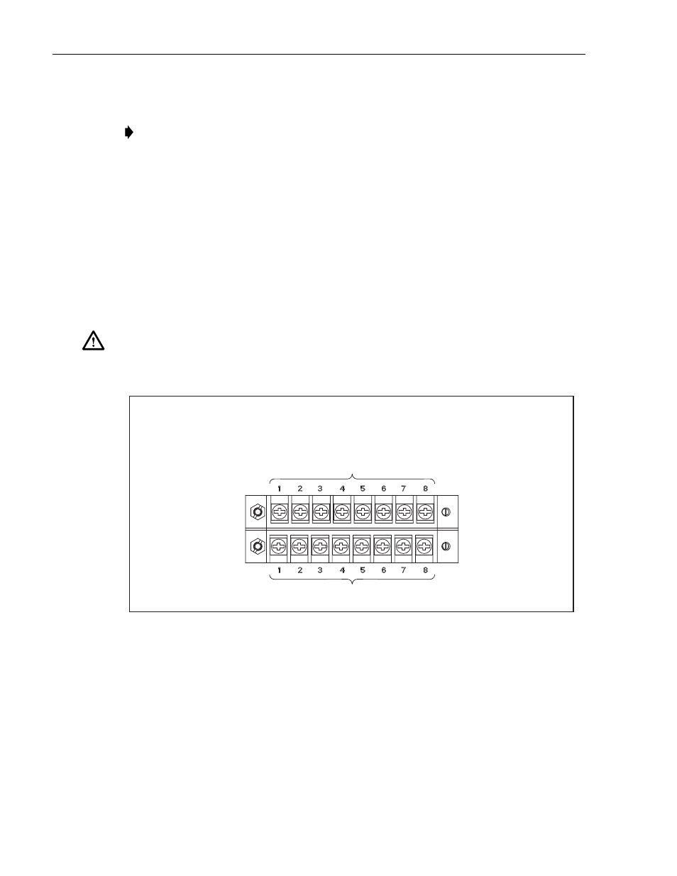
Output Power Connectors
Connect
the output BATT and RTN terminals for each fuse circuit on each set of terminal strips
as
follows (see
):
• Screw-down
barrier terminal strip: Use #12 to #22 AWG wire. Wire leads should be
equipped
with crimp-on spade lugs or ring connectors that have a maximum width of
0.325
inches (8.255 mm).
The
terminals also accommodate copper wire without lugs (insulation stripped back).
Torque
the screws to approximately 9 pound-force inches (1 Newton meter).
• Set
screw barrel terminal strip: Use #12 to #24 AWG wire with insulation stripped back.
Tighten
the screws to approximately 4.5 pound-force inches (1 Newton meter).
Figure 20. Output Connector Connection (Screw-Down Barrier Terminal Strip Connectors Shown)
4.9
External Alarm Contact Connectors
Connect
each set of external alarm contacts to a local alarm system as required (see
Wrap
terminal block pins using #22 to #26 AWG copper wire with insulation stripped back.
Note:
Before connecting the output or input power wires, measure the resistance of each
bus
input connector as specified in
Caution:
For screw-down barrier terminal strip outputs, use #12 AWG wire to prevent
personnel
contact with the voltages (NEBs standard, Class A2).
CONNECT USING CRIMP-ON SPADE LUGS OR RING CONNECTORS THAT HAVE A MAXIMUM WIDTH OF 0.325 IN.
(8.255 MM) ON #12 TO #22 AWG WIRE OR USING #12 TO #22 AWG WIRE WITH INSULATION STRIPPED BACK.
TORQUE THE SCREWS TO APPROXIMATELY 9 POUND-FORCE INCHES (1 NEWTON METER).
16766-A
CONNECT TO OUTPUT POWER CIRCUITS
CONNECT TO OUTPUT RETURN CIRCUITS