7 chassis ground connection, Chassis ground connection – ADC 70 User Manual
Page 25
ADCP-80-524 • Issue 1 • November 2001
Page 25
©
2001, ADC Telecommunications, Inc.
4.7
Chassis Ground Connection
Mounting
the fuse panel on a metal equipment rack using the metal mounting brackets provided
with
the fuse panel provides a sufficient return path to meet equipment grounding requirements.
However,
a separate grounding conductor is often required by local practice or local inspectors.
A
separate chassis grounding conductor is always needed when the fuse panel is mounted to
non-grounded
or non-conducting material such as a plastic rack or cabinet. When the panel
requires
separate chassis grounding, the chassis grounding conductor must be sized to match the
upstream
protection device feeding the panel. This provides an adequate return path capable of
allowing
the fuse to fail in the unlikely event of a battery wire to chassis fault.
Connect
one or both of the chassis ground connectors (labeled C. GND) to the equipment rack
ground
using the following chassis grounding recommendations:
• Chassis
grounding conductor connection point: Two #10 studs (with nuts) on 0.625 inch
(15.875 mm)
centers are provided for connecting a grounding conductor to the fuse panel.
• Chassis
ground conductor: Use two #10 AWG wires if using both chassis ground
connectors
or one #6 AWG wire if using one chassis ground connector. Two #10 crimp
ring
terminals (for use with #10 AWG wires) are included with the fuse panel.
• Place
the ring terminals over the chassis grounding studs and tighten the stud nuts to
approximately
15 pound-force inches (1.7 Newton meters) of torque.
• Connect
the ground conductors to an approved office ground source per local code or
practice.
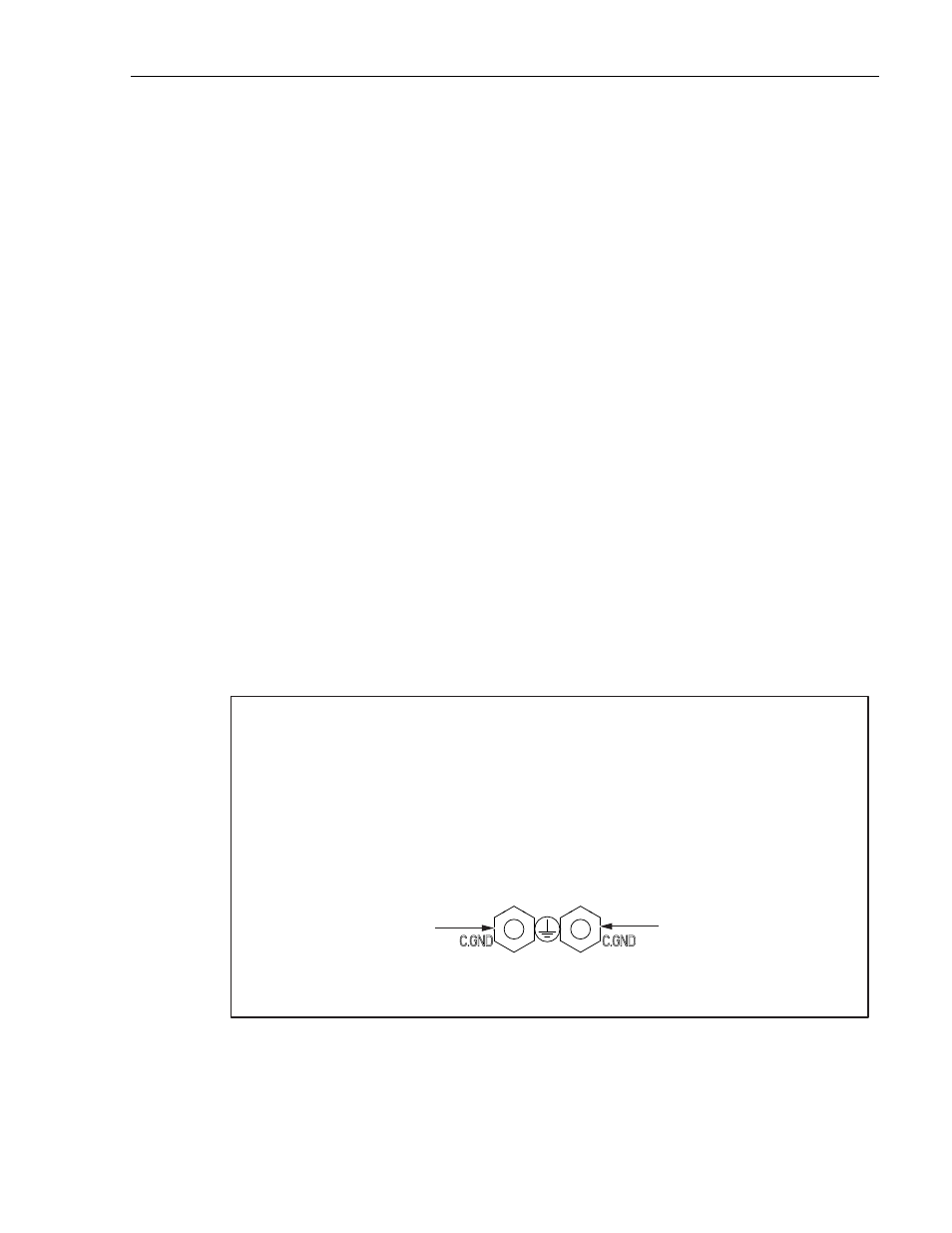
Figure 19. Chassis Ground Connection
USE TWO #10 AWG WIRES IF USING BOTH CHASSIS GROUND CONNECTORS OR ONE #6 AWG WIRE IF USING ONLY ONE
CHASSIS GROUND CONNECTOR.
TWO #10 CRIMP RING TERMINALS FOR ATTACHING THE #10 WIRES TO THE CHASSIS CONNECTORS ARE PROVIDED
WITH THE FUSE PANEL.
PLACE THE RING TERMINALS OVER THE CHASSIS SCREWS AND TIGHTEN THE NUTS DOWN ON THE TERMINALS. IF NOT
USING TERMINALS, WRAP THE WIRE(S) AROUND THE CHASSIS SCREW(S) AND TIGHTEN THE NUTS DOWN ON THE WIRES.
CONNECT THE WIRE(S) TO THE EQUIPMENT RACK.
GROUND SCREW AND NUT
GROUND SCREW AND NUT
16160-A