Wners, Anual, Aintenance – UEi Test Instruments C127OILKIT User Manual
Page 2
S
afety
N
oteS
Before using this meter, read all safety information carefully. In this manual the word “WARNING” is used
to indicate conditions or actions that may pose physical hazards to the user. The word “CAUTION” is used
to indicate conditions or actions that may damage this instrument.
WARNING!
This analyzer extracts combustion gases that may be toxic in relatively low concentrations. These gases are
exhausted from the back of the instrument. This instrument must only be used in well-ventilated locations.
It must only be used by trained and competent persons after due consideration of all the potential hazards.
P
reflight
C
heCkliSt
• Clean particle filter
• Water trap and probe line are empty of water
• Power on and zero
• All hose and thermocouple connections are properly secured
• Flue gas probe is sampling ambient FRESH air
• Water trap is fitted correctly to the instrument
• Flue temperature plug is connected
• Inlet temperature probe is connected if required
a
Nalyzer
C
oNNeCtioNS
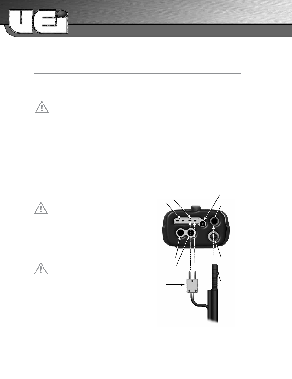
NOTE: Take care when inserting the temperature
probes as the pins are polarized. Insert with the
smaller pin (+) to the right. See diagram to right.
WARNING!
Turning the pump off while the probe is in the flue
will leave toxic gases inside the analyzer. Once data
has been printed or copied it is advisable to purge the
unit with fresh air as soon as possible. To do this,
with the probe removed from the flue, turn ON the
pump. Always allow the readings to return to zero
(20.9 for O2) prior to shutting the unit off. The
meter will not switch off until the CO reading is
below 20 ppm.
WARNING!
The probe will be hot from flue gases. Remove the
probe from the flue and allow it to cool naturally. Do
not immerse the probe in water, as this will be drawn
into the analyzer and damage the pump and sensors.
Once the probe is removed from the flue and the
readings have returned to ambient levels hold down
“On/Off” and switch off the analyzer. The
instrument will count down from 30 to switch off. If
you pressed “On/Off“ by mistake, pressing “Send“
will return you to normal operation.
P
oSt
f
light
• Remove the probe from the flue and allow the analyzer to purge with fresh air until readings return to
zero.
- O2 to 20.9%, CO to Zero (Be careful as the probe tip will be HOT)
• Drain water trap
• Check particle filter
O
WNERS
M
ANUAL &
M
AINTENANCE
Temperature Connections
• Flue Probe Temp: T1
• Inlet Temp: T2
Pressure Connections
• Single Input (Draft): P1
• Differential Input Testing
(Pressure drop test) P2
Flue Probe Temperature Plug
(Plugs into T1)
Narrow Pin MUST be on the
Right hand side.
Battery Charge/AC
Power Adapter
Flue Gas Inlet
Connection
Water Trap drain
Flue Probe Gas Inlet Plug
• Setting Inlet Temperature
- Turn on and zero the analyzer with
out the flue probe connected to use
ambient temperature
- Connect flue probe thermocouple to
T1 during zero countdown to store
probe tip temperature as inlet
(ducted system)
2
3