TOHO ELECTRONICS TTM-10L User Manual
Page 3
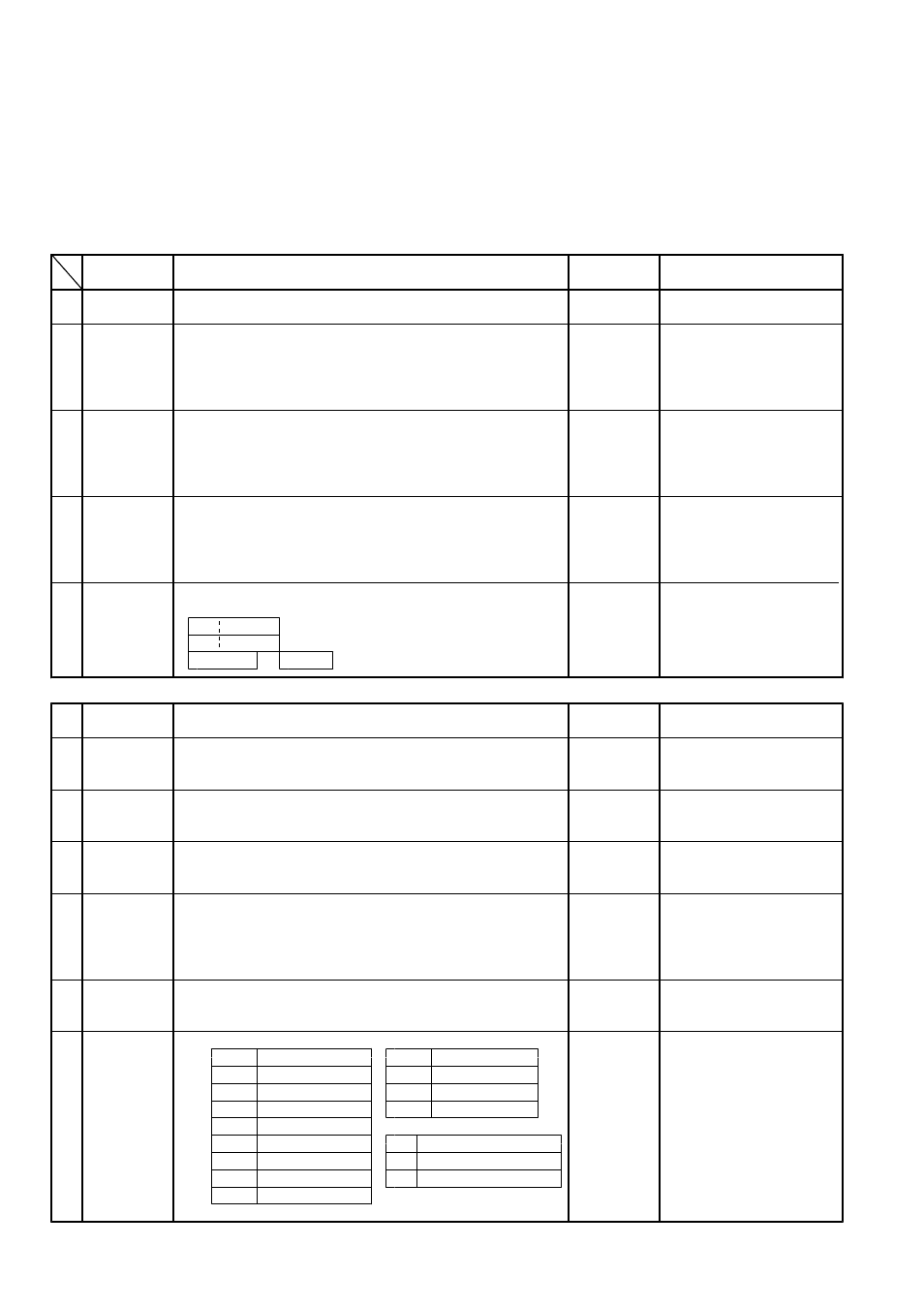
5.3 OTHER DISPLAY INDICATIONS
Shown whenever Input value exceeds the High limit of Display range, or the snapping of the Input line.
:
Shown whenever Input value exceeds the Low limit of Display range, or the snapping of the Input line at 4-20mA.
:
Shown for Memory error. Please contact us for repairing service.
:
Shown for A/D converter error. Please contact us for repairing service.
:
Shown for Auto-tuning error,Push any keys for resetting this display.
:
Shown when Parameter being changed during Key lock.
:
Shown during Auto-tuning.
:
5.4
INFORMATIONS FOR EACH PARAMETER
・MODE Display
Character
Display conditions &
Descriptions
Initial Value
Indications
Remarks
Process
Normal Display after the
A
ariable
Input of Power
V
B
()∼
Shown on PID or
Setting range:SV Limiter Low
SV Limiter High
()
ON/OFF control.
Setting
:1℃(゚F)
Value
Setting unit :Thermocouple
:1/0.1℃(゚F)
R.T.D.
:1/0.1/0.01
Current
Setting range
Thermocouple
Shown when Alarm
C
:
:-1999∼9999
Alarm
R.T.D.
Output s installed and
:-199∼999/-199.9∼999.9
i
Output
Current
set at Low Limit Alarm
:-1999∼9999/-199.9∼999.9/
Setting
Output or High/Low Limit
-19.99∼99.99
Low Limit
Setting unit
Alarm Output.
:Same as that of B.Setting Value.
Setting range
Shown when Alarm
D
:Same as that of C.Alarm Output
Alarm
Output s installed and
Setting Low Limit.
i
Output
Setting unit
set at High Limit Alarm
:Same as that of B.Setting Value.
Setting
Output or High/Low Limit
High Limit
Alarm Output.
Press UP/DOWN key more than 2 seconds for start/reset
Shown on PI
control.
E
D
AT start
of Auto-tuning,(AT)
:
.
display
Shown during AT
:
Shown without AT.
Shown alternatively during A T.
NORMAL
&
:
PARAMETER DISPLAY
Propor-
Setting range
Setting unit
Shown on
control.
1
:0.1∼200.0
:0.1%
PID
tional Band
Integral
Setting range
Setting unit
second
Shown on
control.
2
:0∼3600
:1
PID
Time
Integral operation
at
OFF
=0
Deriva-
Setting range
Setting unit
second
Shown on
control.
3
:0∼3600
:1
PID
tive Time
Derivative operation OFF
=0
at
Output
Setting range
Setting unit
second
Shown on
control.
4
:1∼120
:1
PID
Proportional
Cycle
Setting range
Thermocouple
Shown on ON/OFF
5
:
:0∼9999
Output
R.T.D.
control.
:0∼999/0.0∼999.9
:0∼9999/0.0∼999.9/
Sensitivity
Current
0.00∼99.99
.
..
.
Setting unit
:Same as that of above B.Setting Value
Setting range
Same as that of above
Displays at ON/OFF
6
:
C.Alarm Output
control.
OFF point
Setting Low Limit.
B.Setting Value.
position
:
Setting unit
Same as that of above
The Kind of Output needs
7
**※
Kinds of
to be selected"
"or"
"
**
Input Type
**
Input Type
Pt100
before purchase.
INPUT/
K thermocouple
therm-
J thermocouple
ocouple
OUTPUT
JPt100
E thermocouple
he following Input types
4-20mA DC
INPUT
T
T thermocouple
are NOT selective.
※
Output Type
R thermocouple
4-20mDC
←→
S thermocouple
Relay contact output
thermocouple
INPUT
4-20mADC
N thermocouple
SSR Drive Output
W5Re/W26Re
R.T.D←→4-20mADC