Warning, Caution – TOHO ELECTRONICS TTM-10L User Manual
Page 2
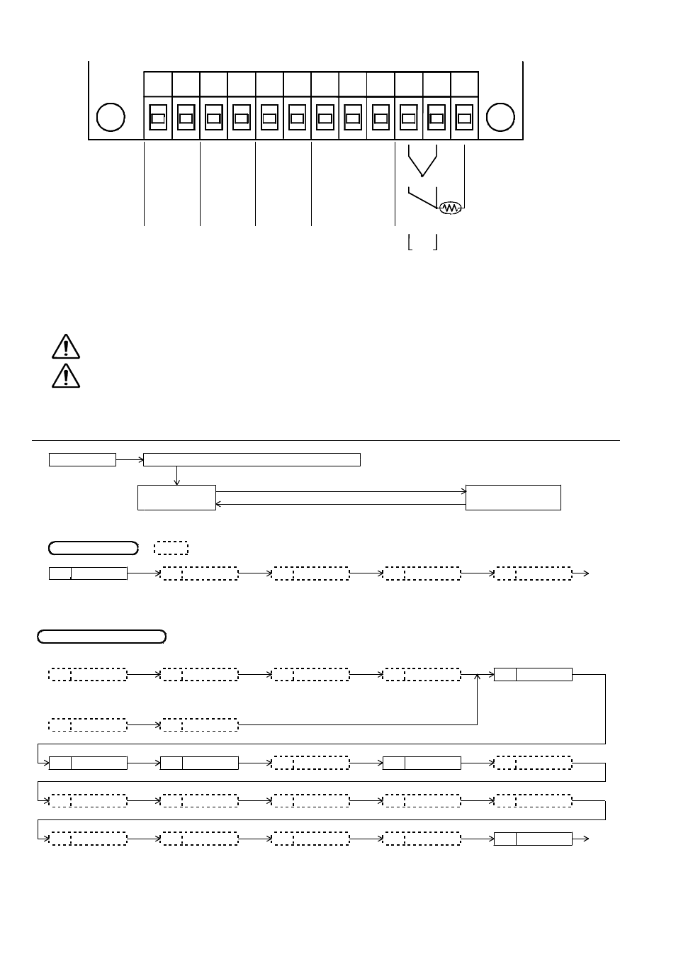
4.2
TERMINAL CONNECTION DRAWING
4.3
CAUTION FOR WIRING CONNECTION
Wiring material with resistance less than 5
per wire should be used to connect R.T.D. with this unit.
・
Ω
The Specified extension lead wire or the wire itself should be used to connect thermocouple with this unit as wiring material.
・
In case this unit should be used close to the noise generators, please use shield-wires.
・
Please do not wire the Input/Output lines inside of the same duct and the pipes of electric wires.
The signal wire of Input/Output should be away from power supply and loaded lines at least 50cm.
・
For prevention of electric shock, please do wiring connection only after turning off Power.
WARNING
・
This unit does not function for approx. 4 seconds after turning on Power. (No function at Output side)
CAUTION
・
For prevention of
, please make sure to confirm the name labels i.e. Input terminal
・
mis wiring
Power source terminal
beside the each wire.
and
etc.
OPERATE FLOW AND PARAMETER INFORMATION
5
5
5
5.
.
.
.
5.1
METHOD TO CHANGE EACH DISPLAY
Power ON
Display type of Input/Output for confirmation
Press Mode Key more than 2 seconds
Mode Display
Parameter Display
Press Mode Key more than 2 seconds
5.2
OPERATE FLOW
shows the existence of Option, or it may not be displayed by the other parameter.
MODE DISPLAY
A
B
C
D
E
Return
Output
to A.
Process Variable
Setting Value
Alarm
Alarm Output
AT Start
Low Limit
High Limit Setting
Display
Setting
PARAMETER DISPLAY
・For PID Control(10.Kind of Control””or””)
1
2
3
4
7
D
Input/Output
Proportional Band
Integral Time
erivative Time
Proportional Cycle
Kind of
・For ON/OFF Control(10.Kind of Control””or””)
5
6
OFF Point Position
Sensitivity
8
9
10
11
12
SV Limiter Low
SV Limiter High
Kind of Control
PV Correction Value
Manual Reset
13
14
15
16
17
℃ ゚
Kind of Communication
Alarm Output Function Alarm Output Sensitivity
Decimal Position
Select
/ F
18
19
20
21
22
Return
Communication
Communication
Communication
Response
to 1 or 5.
Lock Display
Parameter
Speed
Address
Delay Time
12
12
12
12
1
1
1
1
① ② ③ ④ ⑤ ⑥ ⑦ ⑧ ⑨ ⑩ ⑪ ⑫
+
+
+
+
+
+
+
+
−
−
−
−
−
−
−
−
A
A
A
A
B
B
B
B
b
b
b
b
+
+
+
+
−
−
−
−
POWER
POWER
POWER
POWER
SUPPLY
SUPPLY
SUPPLY
SUPPLY
Alarm
Alarm
Alarm
Alarm
Output
Output
Output
Output
SSR
SSR
SSR
SSR
Drive
Drive
Drive
Drive
Output
Output
Output
Output
Communication
Communication
Communication
Communication
Thermocouple
Thermocouple
Thermocouple
Thermocouple
R.T.D.
R.T.D.
R.T.D.
R.T.D.
Current
Current
Current
Current
RS-485
RS-485
RS-485
RS-485
RS-232C
RS-232C
RS-232C
RS-232C
(A)
(A)
(A)
(A) (B)
(B)
(B)
(B)
S.G
S.G
S.G
S.G
(T)
(T)
(T)
(T)
(R)
(R)
(R)
(R)
Relay
Relay
Relay
Relay
Contact
Contact
Contact
Contact
Output
Output
Output
Output
12VDC/
12VDC/
12VDC/
12VDC/
24VDC
24VDC
24VDC
24VDC
−
−
−
−
+
+
+
+