Rm3000 evaluation board overview & set-up, Pcb orientation and output polarities, Rm3000 evaluation board pinout – PNI RM3000 Evaluation Board User Manual
Page 9: Table 4-1: rm3000 evaluation board pin assignments, 1 pcb orientation and output polarities
RM3000 Evaluation Board User Manual
– June 2011
Page 9 of 19
4 RM3000 Evaluation Board Overview & Set-Up
4.1 PCB Orientation and Output Polarities
The arrow printed on the RM3000 Evaluation Board indicates the reference direction for the
module. The sensors are arranged in a north-east-down (NED) coordinate system, and the
arrow is parallel to the x-axis sensor. When the module is pointing directly magnetic south
the x-axis reading will be maximized and the y-axis will be zero. Likewise, when the module
is pointing west the y-axis reading will be maximized and the x-axis reading will be zero.
The z-axis reading will depend on the dip angle at the given location. At the geo-magnetic
equator, where Earth’s magnetic field is horizontal, the z-axis reading will be zero when flat.
4.2 RM3000 Evaluation Board Pinout
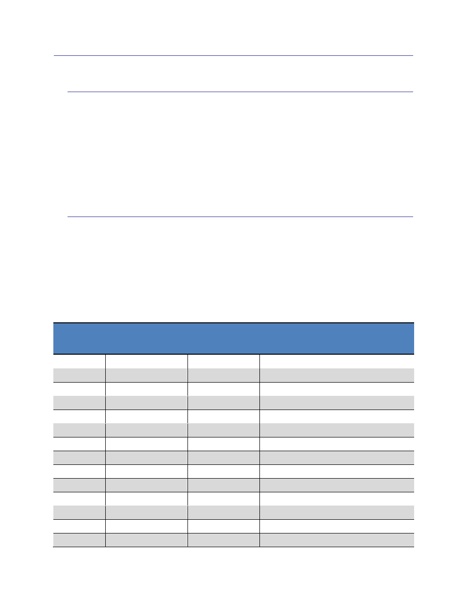
The RM3000 Evaluation Board’s pin assignments are given in Table 4-1. Pin numbers run
counterclockwise (when looking from the top), starting at the Pin 1 designator as shown in
Figure 3-4. Since the board’s labeling differs slightly from standard SPI terminology, the
standard SPI term is also given. This manual will proceed with standard SPI terminology.
Table 4-1: RM3000 Evaluation Board Pin Assignments
Pin#
RM3000 Eval
Board Pin Name
SPI Standard
Pin Name
Description
1
SCK
SCLK
SPI interface - Serial clock input
2
SO
MISO
SPI interface
– Master Input, Slave Output
3
SI
MOSI
SPI interface
– Master Output, Slave Input
4
SSN
SSN
SPI interface
– Active low to select port
5
DRDY
DRDY
Data ready command
6
CLR
CLEAR
Clear Command Register
7
GND
GND
Ground
8
NC
NC
Do not connect
9
NC
NC
Do not connect
10
NC
NC
Do not connect
11
NC
NC
Do not connect
12
Vdd
V
DD
DC Supply voltage
13
NC
NC
Do not connect
14
GND
GND
Ground