Idle mode, Figure 4-1: spi timing diagram, Table 4-2: spi timing specifications – PNI RM3000 Evaluation Board User Manual
Page 12: Figure 4-1, N table 4-2), 4 idle mode
PNI Sensor Corporation
Doc #1015790 r03
RM3000 Evaluation Board User Manual
– June 2011
Page 12 of 19
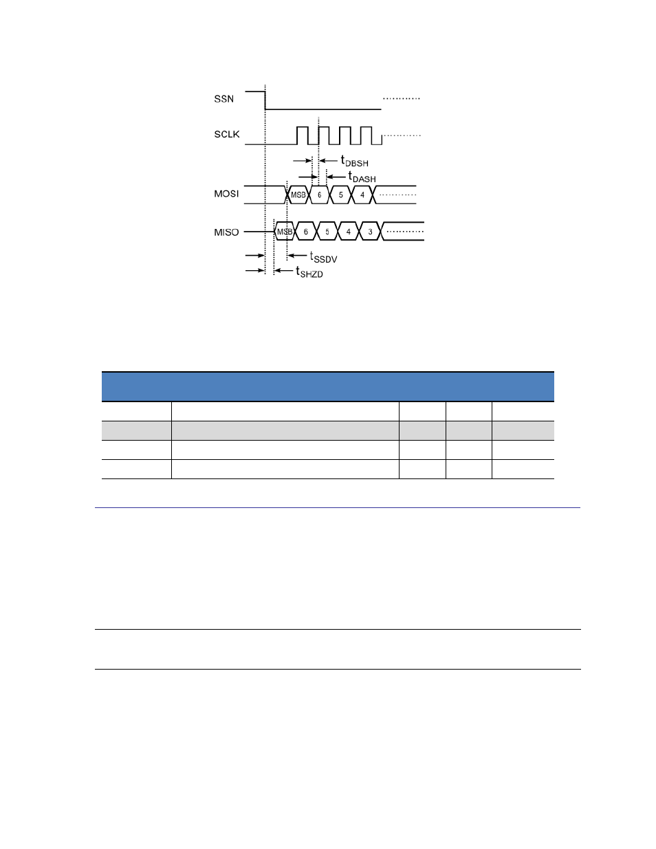
Figure 4-1: SPI Timing Diagram
Table 4-2: SPI Timing Specifications
Symbol
Description
Min
Max
Units
t
SSDV
Time from SSN to Command Byte on MOSI
1
us
t
DBSH
Time to setup data before active edge
50
ns
t
DASH
Time to setup data after active edge
50
ns
t
SHZD
Time from SSN to data tri-state time
100
ns
4.4 Idle Mode
The RM3000 Evaluation Board incorporates an Idle Mode to reduce power consumption, in
which the circuit automatically idles when it is not exchanging data or taking a measurement.
The RM3000 Evaluation Board starts in the Idle Mode at power-up and remains in Idle Mode
until a measurement is needed.
NOTE: The fact that the RM3000 Evaluation Board starts in Idle Mode at power-up is different from
the legacy MicroMag modules, where it was necessary to cycle the MicroMag modules through one
measurement request operation at power-up to put them into Idle Mode.